 Skip to content



The useful purchasing question is not “can this machine run our applicator?” It is: which package surfaces will contact the equipment at each station, what is the reason for that contact, and how will the team confirm that the fine tip remains protected through the sequence? A package-led answer makes trials more meaningful and reduces late changes to change parts.
Why contact-zone definition is a line-design task
An intramammary applicator can travel through feeding, orienting, filling, plunger insertion, capping, inspection and discharge. Each transfer can introduce a different contact pattern. A part may be stable in a feeder yet experience a side load at a transfer, rotate differently in a nest, or meet a downstream guide after it has been filled. Looking at one station in isolation often misses the combination of small contacts that creates marking, deformation, misorientation or intermittent jams.
Fine tips deserve particular attention because they may be narrow, long relative to the barrel, and functionally important in the finished package. A design that uses the tip as a locating pin, an emergency support point or a late-stage guide can create sensitivity to minor dimensional variation. Conversely, a fixture that never controls the barrel body may allow the package to move enough for the tip to strike something else. The goal is controlled support plus deliberate clearance, not simply “no contact anywhere.”
The final design must be based on approved drawings, real samples and customer requirements. Neither a photograph nor a generic component description is a sufficient basis for claiming suitability.
Map the component before choosing tooling
Start with the latest barrel, plunger and cap drawings, together with a small controlled sample set. Mark each external feature as one of four categories: preferred support, permitted light guidance, no-contact zone, or feature requiring confirmation. This creates a common language among package engineering, process engineering, quality and the machine builder.
Typical support candidates
The exact answer depends on the package design, but a barrel flange, a reinforced shoulder, or a cylindrical barrel section may be better candidates than the tip. Support pads should spread load appropriately and avoid sharp edges, burrs or narrow contact points. Where a component has a seam, gate, embossed feature or thin wall, ask whether that detail changes the preferred orientation or pad shape.
Typical clearance candidates
The fine dispensing end, sealing regions, threads, cap-engagement surfaces and cosmetic inspection faces may need clearance or only carefully controlled guidance. “Clearance” should be a designed condition, not a visual guess. A drawing, simple go/no-go check, or observation using the agreed samples can confirm whether the expected gap remains throughout the applicable motion.
Define the product state
A component behaves differently before and after filling. A partly assembled package can also have a different centre of gravity from an empty barrel. Record which state is being reviewed at each station: empty barrel, filled barrel, plunger-present assembly, capped unit or packed unit. This avoids approving a handling contact for a dry sample and unintentionally applying it to a filled package without review.
Create a station-by-station contact map
For each relevant station, make a simple record with five fields: the package state; intended contacts; expected non-contact zones; direction of force or motion; and the observation method. It does not need to be a complex simulation to be useful. Its purpose is to reveal assumptions before tooling is manufactured.
Feeding and orientation
Feeding equipment must present components repeatably without turning normal bulk variation into a jam risk. A guide rail may touch the barrel body, while a tip needs a protected channel with adequate clearance. If components arrive in trays or magazines, document their orientation and the hand-off from packaging to equipment. Component presentation is part of the contact map, not a separate purchasing afterthought.
Indexing and transfer
At an indexer, the fixture has to hold the component against acceleration, deceleration and process loads. Support should remain consistent as the applicator changes direction. If a transfer starwheel or pusher takes over, check whether a previously clear zone comes close to a guide. Slow-motion observation during factory testing can be useful, but it does not replace review of the actual contact geometry.
Filling and assembly
Filling nozzles, plunger insertion axes and cap stations introduce vertical or axial loads. The barrel must be held against those loads at its designated support zones. Ask where the reaction force goes. If the answer is “through the tip,” the tooling strategy needs review. Fine-tip clearance should also be checked after component positioning, not only before the machine begins its cycle.
Inspection and discharge
Inspection cameras, sensors and ejectors should not become unplanned handling devices. A reject mechanism needs a defined, gentle contact point and an understood route for exceptions. At discharge, guide rails and accumulation surfaces should be checked for rubbing or tip collisions, especially when a line slows, stops or restarts.
Specify the fixture, not just the desired outcome
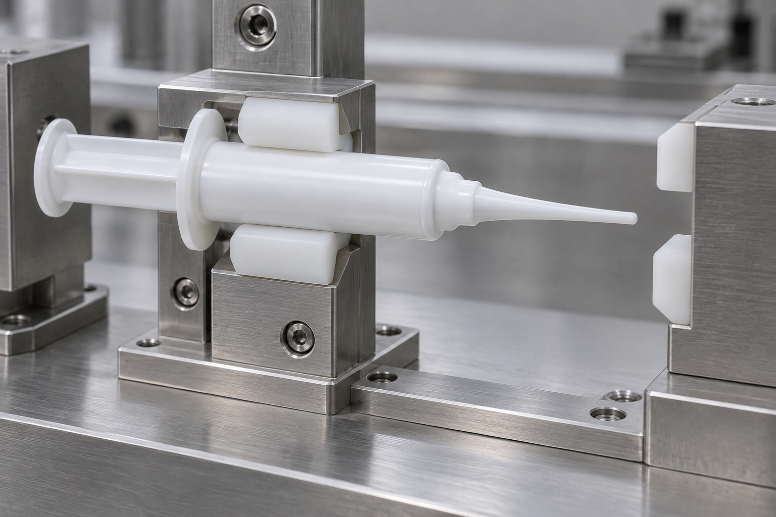
Contact material and geometry
Identify the intended pad or guide material, its finish and its replaceability. Smooth polymer contact pads are often considered for plastic packages, but material choice must match the package, cleaning approach and project environment. The pad shape should match a stable external geometry without trapping a fragile feature. Avoid assuming that a broad-looking support is safe until it has been tried with the actual component.
Location and datum control
State what establishes axial, radial and rotational position. Over-constraining a plastic part can create stress or make the fixture sensitive to routine variation. Under-constraining it can let the package shift into a no-contact zone. The best balance comes from deciding which degrees of freedom actually need control at that station.
Adjustment and change parts
If more than one component format is in scope, document which nests, rails, guide blocks and sensor brackets are format-specific. Change parts should be identifiable and their installation steps should include a practical verification of clearances. Do not describe a fixture as “universal” unless its intended adjustment range has been agreed and checked with representative parts.
Inspection access
The fixture should not hide the exact surface that quality needs to see. If a cosmetic area or tip profile requires inspection, make sure the handling layout allows a camera, sensor or manual check to observe it at the suitable point. A check that is impossible to access reliably is not a meaningful acceptance feature.
CTA — Send Your Requirements: Provide an applicator drawing, sample components and a sequence sketch. We can turn the package into a station-by-station contact-zone review before tooling is finalized.
Convert the review into a buyer-ready requirement list
Procurement works better when the buyer sends a defined information pack instead of a broad request for “careful handling.” Include the current component drawing revision, photographs that show orientation but do not replace dimensions, a list of component lots or samples available for trial, the expected production sequence, and any surface or functional areas that the product owner considers sensitive. If the package will later be packed in a tray, carton or other secondary format, note the expected discharge orientation as well.
The machine proposal should respond at the same level of specificity. It should identify which handling stations are within scope, which features are supported or guided, where format-specific tooling is assumed, and which observations can be made during factory testing. If a requested condition depends on unconfirmed package information, retain it as an open item. That is more trustworthy than silently converting a missing detail into a fixed tooling choice.
Agree the evidence route before the build
Decide how contact-zone evidence will be reviewed: marked-up drawings, a tooling review, photographs of the installed fixture, a witnessed run with supplied samples, or a combination. Define who may approve a change if a trial reveals a necessary adjustment. A concise action log that states the component drawing revision, station, observation, proposed correction and closure evidence prevents the result from being lost between factory testing and installation.
Train for the real intervention points
Operators and maintenance staff do not need a theoretical lesson in fixture design, but they should know which contacts are intentional and which are warning signs. Installation preparation should cover how to identify the correct change parts, inspect pads or rails for wear, return a guide to its confirmed position after cleaning, and segregate any part that has struck a protected zone. Clear visual work instructions can be developed from the agreed contact map once the final tooling is released.
Build the trial around evidence, not a sales demonstration

What to record
Record intended contacts, observed contacts, visible rubbing or marking, tip clearance, component orientation, and the response to a safe simulated exception such as a missing part. Photographs are helpful when they identify the station and sample condition. They should not be used to imply a broader validation claim than the test supports.
Review rejected or stopped parts separately. A mechanism can look stable during steady cycling but behave differently during accumulation or recovery. If a condition is unresolved, list it as an action with the responsible owner and the information needed to close it—such as a revised drawing, additional samples or a tooling change.
Shipment inspection and installation preparation
Before shipment, verify that the agreed fixtures, change parts and relevant documentation are present. The receiving team should have a clear method for storing format parts, matching them to their drawings and preventing mixed sets from being used during installation. During installation preparation, make sure the layout gives operators safe access to guides and nests for cleaning, inspection and changeover.
This is practical evidence management, not an assertion of automatic compliance. Site acceptance, product validation and local quality decisions remain the responsibility of the appropriate project team.
Common mistakes that create avoidable rework
Designing from a photo only
Photographs hide draft angles, local stiffness, dimensional tolerances and packaging variation. Use them as context, but base contact decisions on drawings and representative samples.
Letting the tip become a locator
A tip can accidentally become a locator when the barrel is not constrained or when a guide closes during a transfer. Recheck the condition during motion, not just when the machine is stationary.
Ignoring contact during a stop
Packages may settle differently after an emergency stop, manual intervention or restart. Ask whether clearances and supports remain safe in these non-steady conditions.
Treating cosmetic marks as the only concern
Visible marks matter, but the review should also consider orientation, deformation, transfer stability and whether the package continues to meet the agreed assembly checks. A clean-looking part can still be poorly located.
Translate the contact review into a receiving check
Once the support zones are agreed, identify which component features receiving personnel should compare with the controlled reference. Their role is to recognise an unexpected geometry or supply condition and route it for review, not to redesign tooling at the loading point.
For a revised component, preserve the link between the new drawing, representative samples and affected station. A changed tip or flange may alter clearance even if the barrel’s nominal volume is unchanged. Ask which handling observations need to be repeated before using the existing kit.
Keep the approved contact map with the setup instructions. During maintenance, it helps the team distinguish an intended support surface from an accidental witness mark. During installation preparation, it gives operators a concrete explanation of why a fine tip should not be used as a convenient locating point.
Keep a station-level contact map
A practical map identifies the locating feature and the feature that must remain protected. Use the actual drawings to populate it; the entries below are review questions rather than universal tooling instructions.
| Handling stage | Location question | Protection question |
|---|---|---|
| Incoming separation | Which body feature controls orientation? | Can packing or separation bring tips into contact? |
| Transfer | Where does support pass to the next fixture? | Is the protected zone clear throughout the transition? |
| Station seating | Which approved datum establishes position? | Could component variation reduce clearance? |
| Discharge | What holds the completed assembly? | Does the next guide touch a protected feature? |
FAQ
Which part of a fine-tip intramammary applicator should a fixture hold?
Use the package features identified by its drawing and sample review as suitable support zones, commonly a stable barrel or flange region. Do not assume the tip is suitable for load-bearing contact just because it is easy to locate.
How much clearance should the tip have?
There is no defensible universal number. The clearance must be defined against the component drawing, expected variation, motion and tooling geometry, then checked with agreed representative samples.
Can one fixture handle several formats?
Possibly, but only after the adjustment range, support locations and clearances have been reviewed for each approved format. Format-specific change parts are often clearer and easier to verify.
What should be checked in a factory trial?
Check package location, intended and unintended contacts, fine-tip clearance, transfer behaviour, component orientation and the handling of safe simulated exceptions. Record the exact samples and conditions used.
Does contact-zone review replace package validation?
No. It is an equipment and handling review. Product validation, package qualification and regulatory decisions require the appropriate project evidence and responsibilities.
Conclusion
Fine-tip applicator handling becomes more controllable when contact is designed rather than assumed. Map the package, state the allowed supports and protected zones at every station, and use representative components to verify the actual motion. That approach creates a clearer equipment specification, a more useful factory test and fewer surprises during installation.
CTA — Ask for Product Review: Send the component drawing, samples and intended line sequence. We will help identify the tooling contacts, clearances and trial evidence needed for your intramammary applicator project.
—
Related King Pack resources
For equipment selection, see our syringe filling machine solutions, veterinary medicine filling equipment, and veterinary and animal-health packaging solutions. For intramammary projects, compare the intramammary syringe filling line with dosing paste syringe filling. See also our guides on component presentation, site-acceptance preparation, and batch component reconciliation. For the wider line, review filling and capping line solutions, packaging equipment solutions, and veterinary filling and capping applications. Send your requirements through the Contact Us page or request a quote form.
