 Skip to content

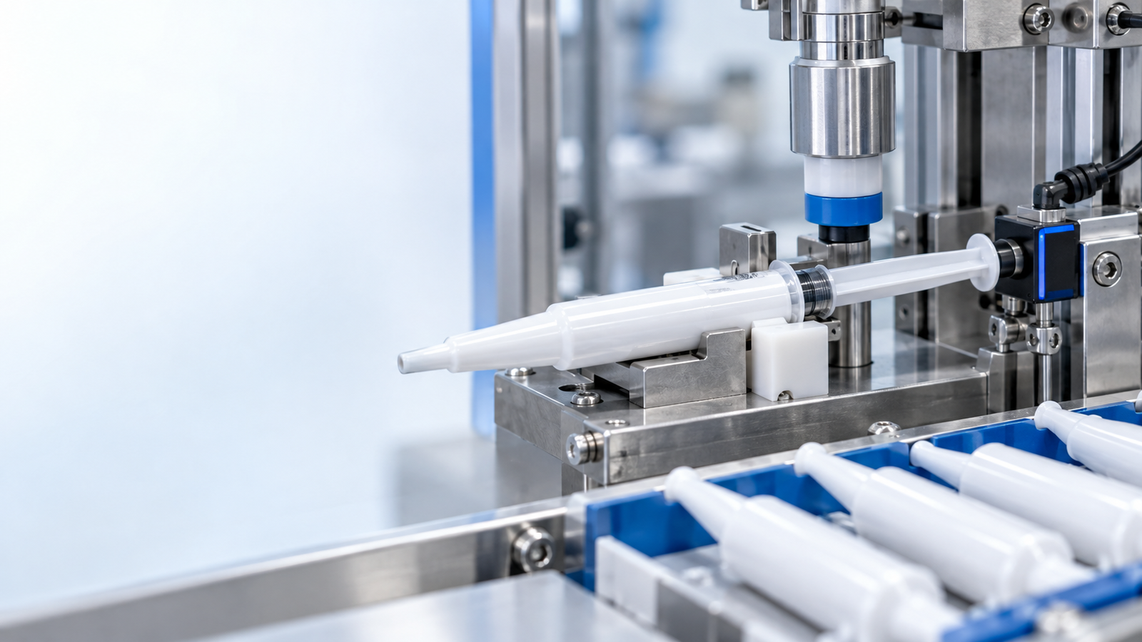

AI-generated illustration: define plunger insertion support, travel and final position.
Plunger insertion in an intramammary applicator is not simply a final push. It is a package-assembly step that has to preserve barrel geometry, avoid uncontrolled product displacement, and leave a repeatable, inspectable end position. The correct specification starts with the actual barrel, plunger and fill state—not with a generic insertion stroke.
For most projects, the useful question is: what contact points and travel limits will seat this plunger without loading a fine tip, distorting the barrel, or masking an incorrectly seated component? The answer should be captured in drawings, samples and a trial protocol before a line is released for factory testing.
Why plunger insertion deserves its own specification
An intramammary package combines a relatively long plastic barrel, a narrow dispensing end and a plunger that may be introduced after filling. The assembly station therefore links several functions: component presentation, barrel locating, filling hand-off, plunger pick-up, guided entry, controlled seating and discharge. A problem at this point can look like a filling, cap, conveyor or component issue later in the process.
The risk is not limited to a visibly crooked plunger. A barrel that is not supported at the intended structural zone can flex during insertion. A plunger that begins slightly off-axis can touch the bore unevenly. A travel stop that is based on cylinder stroke rather than the real package datum can hide normal component variation or push beyond the intended position. If the product is viscous, air-sensitive or filled close to the final plunger position, the insertion profile can also influence the practical conditions seen by the product and package.
This does not mean every project needs a complex servo axis or a universal numerical force limit. It means the supplier and buyer should define the physical decision points. Final settings depend on the supplied components, formulation behaviour, customer quality requirements and the agreed trial samples.
Begin with the package stack, not an assumed machine stroke
Before selecting a plunger-insertion mechanism, assemble a controlled sample set. It should include representative empty barrels, plungers and caps; filled samples where it is safe and appropriate; the latest component drawings; and any stated acceptance criteria. When multiple component lots are planned, record their identity separately. A trial that mixes unknown lots may produce observations, but it does not reliably tell a team whether variation comes from the machine or the component set.
Identify functional datums
The team should agree which package features the tooling may use as stable reference points. Common candidates include an external barrel flange, a reinforced shoulder or a defined cylindrical body zone. The tapered tip is usually a poor primary locating feature: it is more delicate and may be functionally important to downstream use. The internal bore and sealing features also need respect; a fixture should not make assumptions about them without component data.
Ask four practical questions during design review:
- Which external feature establishes axial position?
- Which surfaces are acceptable for radial support?
- Where must the tooling provide clearance rather than contact?
- What finished plunger location is meaningful for the package and downstream inspection?
These questions turn “insert the plunger” into an engineering requirement. They also prevent a late-stage argument in which the machine is tuned around a sample that no longer represents production supply.
Treat component variation as an input
Plastic components can vary within their agreed drawings. The purpose of the station is not to erase that variation by excessive force or an over-constrained nest. Instead, the station should tolerate the agreed variation while keeping the component controlled. For a purchasing specification, request the drawing revision, sample quantity, material information where relevant, critical dimensions and the method used to communicate changes. The equipment builder can then identify where adjustable guides, format parts or a controlled verification step may be needed.
Define the insertion sequence in observable stages
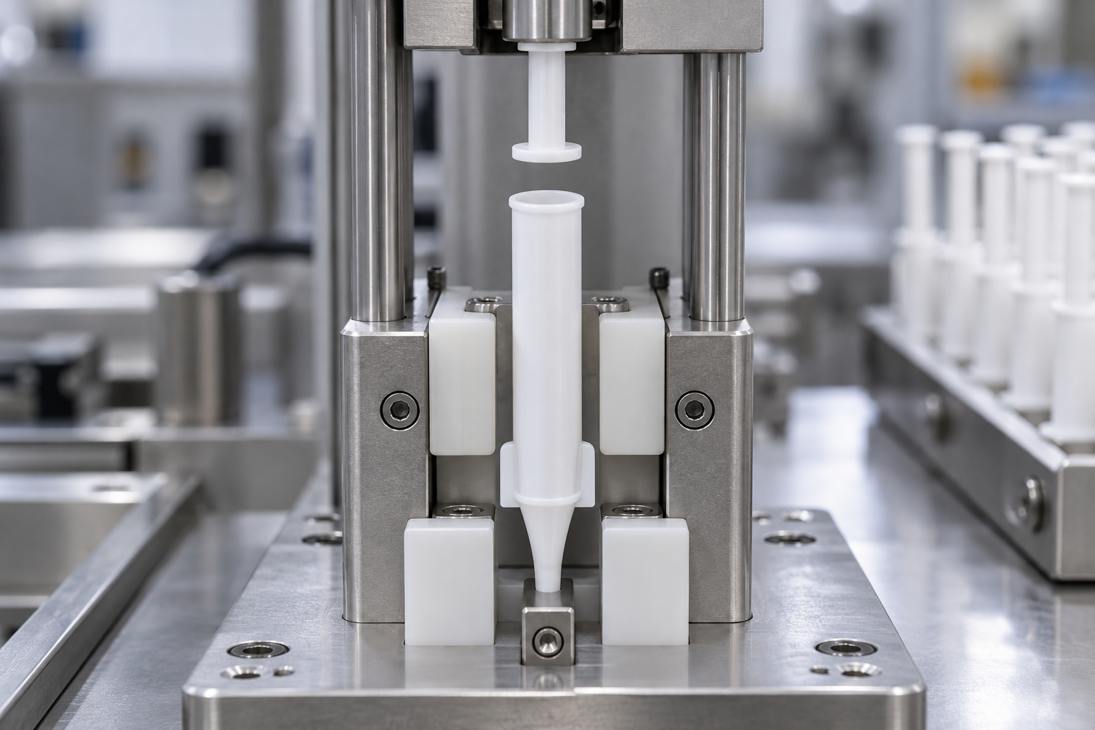
AI-generated illustration: A guided approach and barrel support help make the plunger entry condition observable.
A well-specified station has stages a team can watch, describe and test. The exact mechanics can differ, but the logic is useful across line layouts.
1. Present and orient the barrel
The barrel must arrive at the station in the intended orientation and be retained without side loading. A guide that works on an empty, rigid-looking sample may behave differently after filling or when a minor dimensional change is present. In factory testing, observe not only whether the barrel arrives, but whether it settles consistently at the locating datum before the plunger approaches.
2. Support the barrel at the designed zones
Support should resist the insertion load where the component can carry it. Contact pads, nests and clamps must be shaped to avoid sharp local loading. Where the package includes a fine tip, a clearance check is often more useful than a contact check: confirm that the tip does not become an unintended third support point when the barrel is clamped or transferred.
3. Pick up and guide the plunger
The pickup method must present the plunger in a repeatable orientation. A plunger can be perfectly acceptable as a component and still enter poorly if it is released too early, guided too late or allowed to swing during travel. The first part of motion should establish alignment before the sealing or seating condition is engaged. If a vacuum, gripper or mechanical pickup is used, verify release behaviour on representative parts rather than assuming a nominal part is sufficient.
4. Control the approach and insertion travel
Approach travel and seating travel are related but not identical. The approach brings the plunger to the barrel in alignment; the controlled insertion moves it to the agreed location. A hard mechanical stop, a programmed axis position, or a combination of both may be appropriate. The key is traceability: the team must be able to say what the reference is and how it was checked.
For product-contact applications, do not infer performance from a single dry run. The practical insertion profile should be evaluated with the product or an agreed representative medium only when that is part of the customer’s test plan. The equipment supplier should document what was actually tested and what was not.
5. Verify end position and reject or segregate exceptions
End-position verification does not need to promise measurement precision that has not been validated. It should, however, distinguish an obviously incomplete, missing, tilted or over-travelled assembly from a normal part within the agreed condition. Possible methods include a mechanical feeler, a height or presence sensor, a vision check, or a downstream quality check. The selected method must be matched to the feature it is asked to judge.
CTA — Send Your Requirements: Share the barrel, plunger and cap drawings, representative samples and your intended inspection point. We can review the package sequence and identify the questions to close before a factory trial.
Choose an end-position definition that the production team can use
“Fully inserted” is rarely enough. It may mean a plunger flange is flush to a reference plane, a plunger rod reaches a nominal travel, a functional seal reaches a defined location, or a cap fits after assembly. These are different conditions. A useful specification names the observable feature and the reference feature.
Use package-led language
For example, a requirement can state that the plunger position is assessed relative to a defined external barrel datum on representative assemblies, using the agreed inspection method. That is more actionable than demanding a generic millimetre number when the component drawing, fill level or measurement method has not been finalized.
The acceptance protocol should also state what happens to a suspect part. Is it rejected automatically, placed in a segregated container, held for manual review, or used only during setup? Clear exception handling is as important as the normal motion because it keeps an intermittent event from becoming a mixed-batch issue.
Keep checks proportionate
Not every line needs every sensor. More sensing is not automatically better if it is sensitive to normal component variation or difficult to maintain. During a design review, rank checks by the failure mode they address. A missing-plunger check answers a different question from a seating-depth check. A vision system may help document orientation, while a mechanical stop may define travel. The final combination should reflect the product, risk review, output expectation, operator workflow and customer requirements.
What to review at factory testing

AI-generated illustration: Shipment inspection and installation preparation should verify the actual tooling and samples used.
Factory testing is most useful when it follows an agreed observation list rather than a general demonstration. Bring or supply representative barrels and plungers; confirm their lot identification; and record the actual format parts, settings and samples used. A practical review list includes:
- Barrel location before plunger approach and support during seating.
- Clearance around the fine tip and any features designated as non-contact zones.
- Plunger pick-up, alignment, release and visible entry into the bore.
- Repeatability of the defined end-position check across representative samples.
- Response to an intentionally missing, incomplete or obviously misaligned component where safe to simulate.
- The path for accepted, rejected and manually reviewed assemblies.
- Changeover steps if another package format is within the project scope.
Record observations honestly. A successful test on the supplied samples is evidence for those samples and the agreed test condition; it is not a substitute for site qualification, product validation or regulatory approval. Where a result depends on a pending drawing or later formulation, list that dependency rather than turning it into an implied guarantee.
Prepare installation before the equipment arrives
Installation preparation often starts with documents rather than tools. The receiving site should have the latest layout, utilities list, access route, sample plan, component storage arrangement and named contacts for engineering, quality and operations. The team should also decide where sample components will be kept and how their status will be controlled during startup.
At shipment inspection, confirm that format parts, sensors and documentation correspond to the ordered configuration. Photograph or list packed change parts according to the project procedure. Do not rely on memory after crates have been opened on site. This simple discipline makes later troubleshooting faster because the team can distinguish a missing installation item from a process setting question.
Common specification mistakes
Using force as the only acceptance condition
Force may be useful as a monitored process signal where the equipment and package justify it, but it does not replace position, alignment or component review. A force trend can change because of lubrication, temperature, component variation, pickup conditions or product behaviour. Define the decision logic before treating a force reading as a pass/fail rule.
Supporting the tip because it is easy to locate
The narrow end can be visually convenient, yet it is often not the best load-bearing reference. Ask the component designer which surfaces are intended to tolerate handling. Build clearance into the tool where contact is not intended.
Reviewing only empty components
Empty parts are valuable for mechanical setup, but a project involving filled applicators must consider how filling and assembly interact. Decide in advance whether a representative filled sample, agreed surrogate or dry mechanical test is appropriate. State the limits of the test evidence in the report.
Treating a trial as the end of change control
A trial sets a baseline. It should feed a controlled record of drawing versions, format parts, component lots, settings and accepted observations. When a component design changes, review the impact before assuming the previous settings remain applicable.
Keep the insertion baseline accessible after handover
Store the approved barrel and plunger combination with its drawing references, format kit and inspection method. Identify the setup evidence produced during factory testing and the observations confirmed at site. This makes a future insertion question traceable to actual components instead of a nominal package size.
If the customer changes the plunger supplier, material or mating geometry, review the affected interface before reusing the previous setup. A visibly similar component can behave differently at location or during insertion. Record the change and the checks needed under the customer’s procedures.
During shipment inspection, confirm that supplied insertion tooling matches the agreed parts list. During installation preparation, make the relevant samples and current references available to the commissioning team. These activities support continuity; neither one establishes product release or a universal insertion-performance claim.
Link insertion observations to their references
Keep observations specific enough that another reviewer can understand the setup. The record should separate mechanical location from customer-owned product assessments.
| Observation | Reference to preserve | What it does not establish alone |
|---|---|---|
| Barrel seating | identified barrel and installed nest | compatibility of an unreviewed future format |
| Plunger approach | plunger identity and station configuration | universal insertion behaviour |
| Final visible position | agreed inspection reference and viewing point | product quality or dose performance |
| Changed setup | authorised adjustment and first-piece result | acceptance without the relevant checks |
| Trial outcome | actual components and test conditions | all future component-lot outcomes |
FAQ
What is the most important reference for plunger insertion?
The most important reference is the agreed package datum that reflects how the barrel should be held in real production. It is usually a stable external feature, not the fine dispensing tip. The component drawing and sample review should confirm the final choice.
Can an end-position sensor prove that the package is acceptable?
It can provide evidence for the specific condition it is designed to detect. It cannot by itself prove all package functions, product performance or compliance. Its role and limits should be stated in the test protocol.
Should the same tooling be used for every plunger lot?
Only if the approved drawings, dimensions and trial evidence support it. A change in component geometry, material or tolerance can require a review of guides, settings, contact zones or inspection thresholds.
Is a filled trial always required?
No. The appropriate trial depends on the project scope, product behaviour, safety controls and customer requirements. Where a filled or surrogate trial is planned, document the material and conditions used rather than extrapolating from a dry run.
What should be available before a factory acceptance test?
Provide current drawings, identified representative components, the intended acceptance checks, a list of simulated exceptions if any, and the contacts empowered to agree observations. That makes the test a decision point instead of a generic machine demonstration.
Conclusion
Reliable intramammary applicator plunger insertion is designed around the package: stable barrel support, protected non-contact zones, guided plunger entry, a defined travel reference and an inspection method that answers a specific question. The strongest projects make those choices visible in samples, tooling review and factory-test records before installation.
CTA — Get a Quote: Send your package drawings, component samples and target process sequence. We will help scope an intramammary applicator line around the checks and tooling questions that matter to your project.
—
