 Skip to content

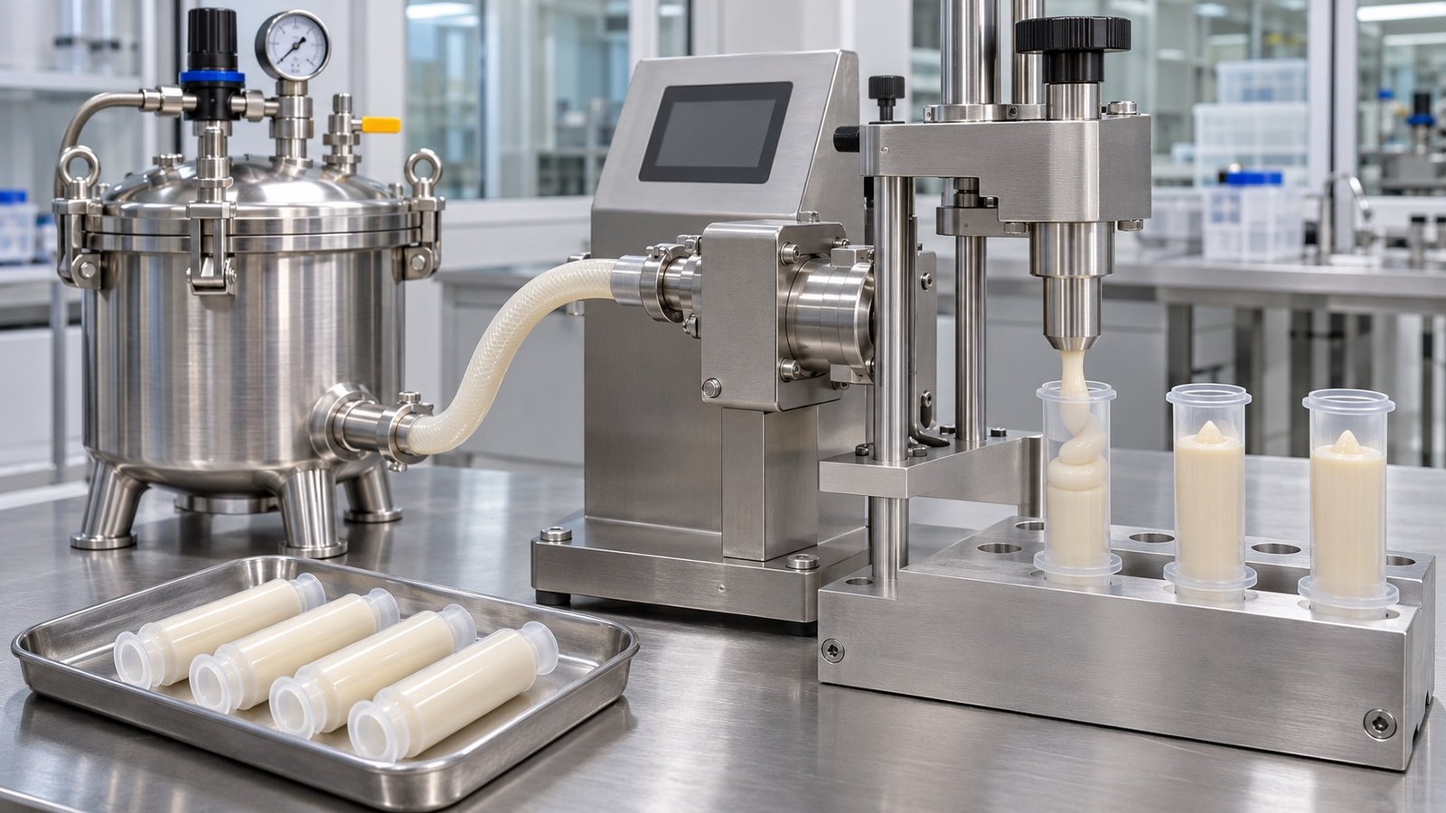
A suitable dental composite syringe filling machine needs more than a pump that can move thick paste. It must keep a particle-filled, potentially light-sensitive material supplied to the metering chamber, fill a small applicator without folding in unacceptable air, cut off cleanly, insert the closure without disturbing the dose and produce repeatable results after startup, stops and restarts. The correct setup can be selected only from the actual composite, package and acceptance protocol.
This article focuses on high-viscosity restorative composite in needle-free dispensing syringes. It is a deeper engineering question than choosing equipment for dental materials in general. It does not claim that every composite behaves alike or that a standard King Pack model is already qualified for this application.
Why dental composite is not an ordinary paste
Dental restorative composites contain a resin matrix and inorganic filler. In its technical product profile, 3M states that Filtek Universal Restorative has about 76.5% inorganic filler by weight, is visible-light activated and is offered in 4 g syringes as well as unit-dose capsules. This is one documented product example, not a universal specification for all composites.
A peer-reviewed review of rheological and mechanical properties of dental resin materials explains that filler content and particle characteristics influence viscosity. Higher filler loading often increases viscosity, but particle size, shape, distribution and the resin system also matter. Therefore, a buyer should not specify equipment from a single viscosity number or from a competitor's material data.
The machine supplier needs the actual formulation at the normal processing condition. If several shades or formulations will use the same line, each one belongs in the feasibility matrix.
Characterize the composite before choosing the filling system
Viscosity is useful, but it is not the whole material description. A dense composite can show yield behavior, shear thinning, recovery after shear and temperature sensitivity. The value reported by a laboratory also depends on test method, shear condition and temperature.
Prepare a data pack covering:
- material name or internal code and shade range;
- viscosity or rheology method and test temperature;
- filler or particle information relevant to wear and restrictions;
- density at the intended filling temperature;
- sensitivity to light, heat, moisture or extended hold time;
- storage, warming and conditioning instructions;
- batch size and time out of controlled storage;
- approved contact materials and cleaning agents;
- safety data and waste-handling requirements.
The 3M instructions for Filtek Universal Restorative state that the product is designed for use at room temperature, should be allowed to reach room temperature after refrigerated storage and should not be exposed to intense light. Apply only the actual formulation owner's instructions to the production project. Do not copy another product's temperature or light limits.
Design a low-resistance, continuously supplied product path
The metering device cannot deliver a stable small dose if its inlet alternates between fully supplied and starved. A dense composite may bridge in a hopper, retain air after transfer or require excessive pressure through a long narrow hose. The supply arrangement should keep the product column continuous without uncontrolled compression or shear.
Evaluate the entire route:
conditioned bulk material → feed vessel or cartridge → pressure or follower system → short transfer path → metering device → valve → filling nozzle
Useful design questions include:
- Can the bulk container be loaded without creating folds or air pockets?
- Is pressure applied uniformly to the product surface?
- Are hose length and bore adequate for the material at the intended temperature?
- Can every connection be inspected, cleaned or replaced?
- What happens when the bulk container approaches empty?
- How is the line primed, and where does the priming material go?
- Does the supply recover after a planned stop without a manual adjustment?
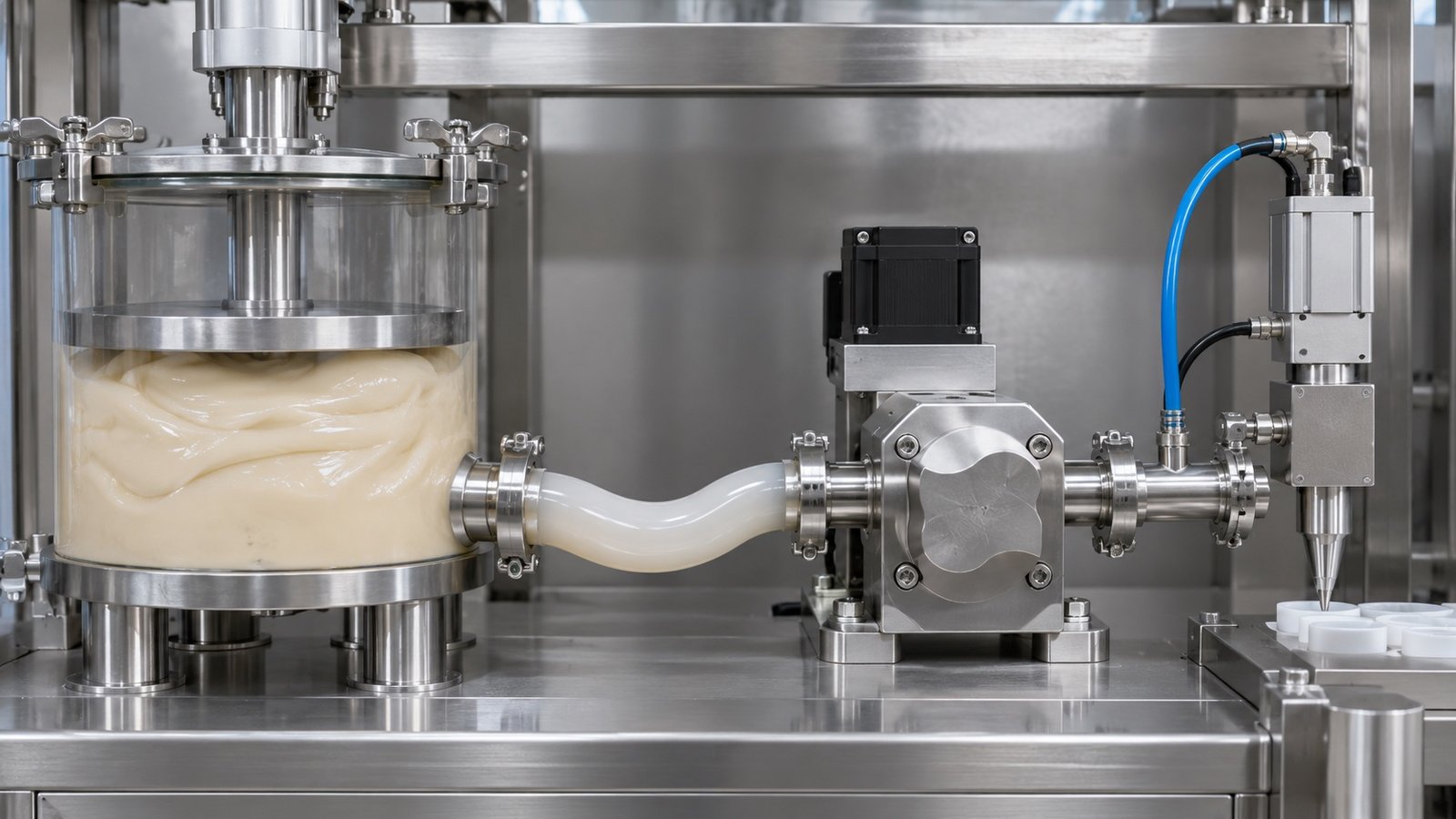
The site's high-viscosity syringe filling system guide expands this product-path review from the bulk container to the nozzle.
Match the dental composite syringe filling machine to small doses and dense material
For a particle-filled composite, buyers commonly evaluate positive-displacement metering because the device moves a defined chamber or rotor volume. That principle does not guarantee the final result. Inlet conditions, material compression, valve timing, nozzle cutoff and package handling still affect the filled unit.
Ask the supplier to show:
- how the metering chamber fills at the lowest intended supply level;
- the minimum and maximum practical dose for the selected hardware;
- how recipe changes affect stroke, speed or rotation;
- how pressure is monitored and what constitutes an alarm;
- which wear parts contact the composite and how they are inspected;
- how the system is purged without exposing excessive material to light or residence time;
- whether the pump can be disassembled and reassembled repeatably after cleaning.
Avoid specifying a pump solely from a catalog accuracy value. Accuracy at the package level must be established with the real composite, barrel, feed pressure, cutoff and measurement method.
Use the largest practical nozzle and controlled filling motion
A narrow nozzle increases resistance and may require more pressure. A wide nozzle reduces restriction but must fit the applicator opening and leave enough clearance for air to escape. The practical choice balances product flow, barrel geometry, cutoff and cleanliness.
Bottom-up filling can reduce the distance that dense composite falls and can keep the nozzle outlet near the rising product surface. Nordson EFD's guidance for manually filling high-viscosity syringe barrels recommends bottom filling for particle-filled pastes and warns that excessive fill rates can introduce air even with this technique. That guidance supports the process principle; an automated dental application still needs its own trial.
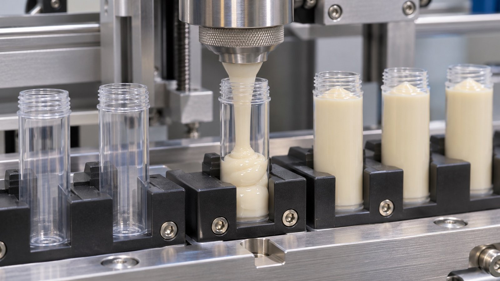
Use the filling nozzle selection guide to structure trials for bore, insertion depth, withdrawal speed and cutoff. Record pressure and residue as well as dose.
Control air before and during filling
Air can already exist in the bulk material, enter during loading, leak through a connection, appear when the pump inlet is starved, or become trapped by the filling motion. These causes require different corrective actions. Vacuum is not the automatic answer.
Nordson EFD notes that bubbles in syringe systems can come from trapped air, product thawing and air bypass during high-speed dispensing of thick paste. Its guidance also discusses degassing and piston selection. For an industrial line, first map the point where the bubble appears, then test the relevant response.
Compare these options under one protocol:
| Observed condition | First checks | Possible trial response |
|---|---|---|
| Air visible in bulk composite | Mixing, conditioning, container loading | Revised bulk preparation or degassing approved by the formulation owner |
| Pump inlet intermittently empty | Container geometry, follower contact, hose restriction | Improved pressure-assisted feed or shorter product path |
| Pocket forms during barrel filling | Nozzle depth, fill rate, withdrawal and vent path | Bottom-up motion, revised rate or nozzle bore |
| Pocket appears after piston insertion | Headspace, piston fit and insertion sequence | Revised fill level, venting or controlled stoppering trial |
| Defect increases after a stop | Residence time, pressure recovery and cutoff | Defined restart purge and acceptance procedure |
If conventional controls cannot meet a defined visible-air or headspace limit, use the vacuum-assisted filling selection guide to plan a controlled comparison. Keep vacuum filling and vacuum stoppering as separate functions.
Define package-level acceptance, not only pump output
A dental composite applicator has several relevant outputs. Net content matters, but so do visible air, product surface, residue, piston position, cap seating and end-use dispensing behavior. A good scale result can still hide an unacceptable pocket or closure position.
Develop an acceptance sheet with:
- tare method and net-mass calculation;
- density reference if mass is converted to volume;
- sampling plan and treatment of startup or restart units;
- controlled lighting, orientation and magnification for visible-air inspection;
- maximum permitted residue on the barrel, flange and cap;
- piston insertion-depth or position window;
- tip-cap seating and leak or package-function method;
- response to an alarm, intervention or rejected unit.
Do not invent an accuracy target from the machine category. The product owner and quality team should set limits that relate to the labeled quantity, package function and applicable quality system.
Test startup, steady operation and restart separately
Averages can conceal the most important conditions. A trial should keep startup, stable running, replenishment and restart samples in separate groups. Use the same product lot and component lots when comparing machine settings.
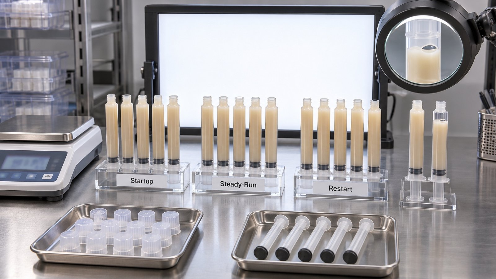
A useful trial matrix includes:
- normal loading and priming;
- at least one stable-running sample group;
- a bulk-container replenishment or change;
- the shortest planned stop and restart;
- the longest routine stop before cleaning or disposal;
- the lowest intended product level in the supply container;
- each applicator size and the most difficult composite shade or formulation;
- closure insertion and downstream handling.
Record material temperature, time since conditioning, feed pressure, dosing setting, nozzle motion, unit mass, visible-air result, closure position, rejects and operator interventions. Video of the nozzle and product surface can help explain a defect, but it does not replace measured samples.
Integrate piston insertion and tip closure with the fill
The applicator closure sequence can compress headspace or disturb the product. Define whether the tip is closed before rear filling, whether a piston is inserted after filling, and when the plunger rod is assembled. Confirm how the barrel is supported against the closure load.
For each closure, specify:
- orientation and feeding method;
- presence and position checks;
- allowable insertion depth or cap seating window;
- venting path during piston insertion;
- reject logic after missing or skewed components;
- product-contamination risk to closure tooling;
- cleaning and access after a spill.
The package drawing should control the tooling design. A similar-looking syringe from another supplier may have different flange, thread or piston tolerances. Review the syringe format changeover guide before promising that several applicators can share one tool set.
Select automation only after the process window is stable
A benchtop or semi-automatic system can be appropriate while the product path, nozzle motion and closure sequence are still being developed. Automatic feeding and multiple stations become more valuable after the package and process window are stable.
Moving to a faster index does not solve a starved inlet, trapped air or poor cutoff. It can make the defect more frequent. Establish the fill and closure method first, then size the automation from batch demand, labor content, changeover frequency, inspection method and downstream packaging.
The automatic versus semi-automatic syringe filling guide helps buyers compare development flexibility with integrated handling. If multiple filling heads are being considered, use the filling-head quantity guide to account for balancing, cleaning and head-to-head verification.
What to request from King Pack
King Pack has confirmed experience with syringe filling equipment, custom configuration, FAT, documentation, training and line integration. Dental composite suitability remains unconfirmed until the engineering team reviews the formulation, applicator and trial data. No catalog filling range or general “ointment” statement should be treated as proof for a particle-filled restorative composite.
Send the following for review:
- product data and safety information;
- normal and worst-case material samples;
- complete applicator and closure drawings plus component samples;
- target dose and batch profile;
- light, temperature, hold-time and cleaning constraints;
- proposed visible-air, dose, closure and package-function criteria;
- desired automation level and downstream interfaces;
- FAT sample groups and documentation expectations.
Review the syringe filling equipment categories and contact King Pack with the product-and-package data pack to arrange a feasibility assessment and representative trial.
Frequently asked questions
Which pump is best for dental composite syringe filling?
There is no universal answer. A positive-displacement method is often evaluated for dense paste, but the feed condition, particle content, dose, wear, cleanability and nozzle cutoff must be tested together.
Is a viscosity value enough to select the machine?
No. Include the measurement method and temperature, plus yield, shear-recovery, density, filler, light and hold-time information where available. Representative samples are still required.
Does bottom-up filling guarantee no bubbles?
No. It can reduce one source of air entrainment, but air may already be in the material or enter through loading, transfer, a starved inlet or piston insertion. Test each cause separately.
Should dental composite be warmed before filling?
Only if the formulation owner permits and defines the method. Do not apply another product's clinical warming instruction to production filling without documented approval and a controlled trial.
How should fill accuracy be checked?
Use an agreed tare and net-mass method, a calibrated balance and a sampling plan that separates startup, steady operation and restart. If converting mass to volume, use verified density at the relevant temperature.
Can a standard syringe filler be ordered before a material trial?
That is risky. The nominal dose range does not establish feed, wear, air control, cutoff, cleaning or closure performance with a filled composite. Complete feasibility review and representative testing before final configuration.
