 Skip to content

Choosing a liquid filling machine is not a matter of comparing headline speed or selecting the lowest quoted price. The correct system is determined by six connected inputs: product behavior, required fill range, container geometry, closure format, target output and cleaning or compliance requirements. If even one of these inputs is missing, a machine that appears suitable on paper may foam, drip, trap air, damage containers or become too slow during changeover.
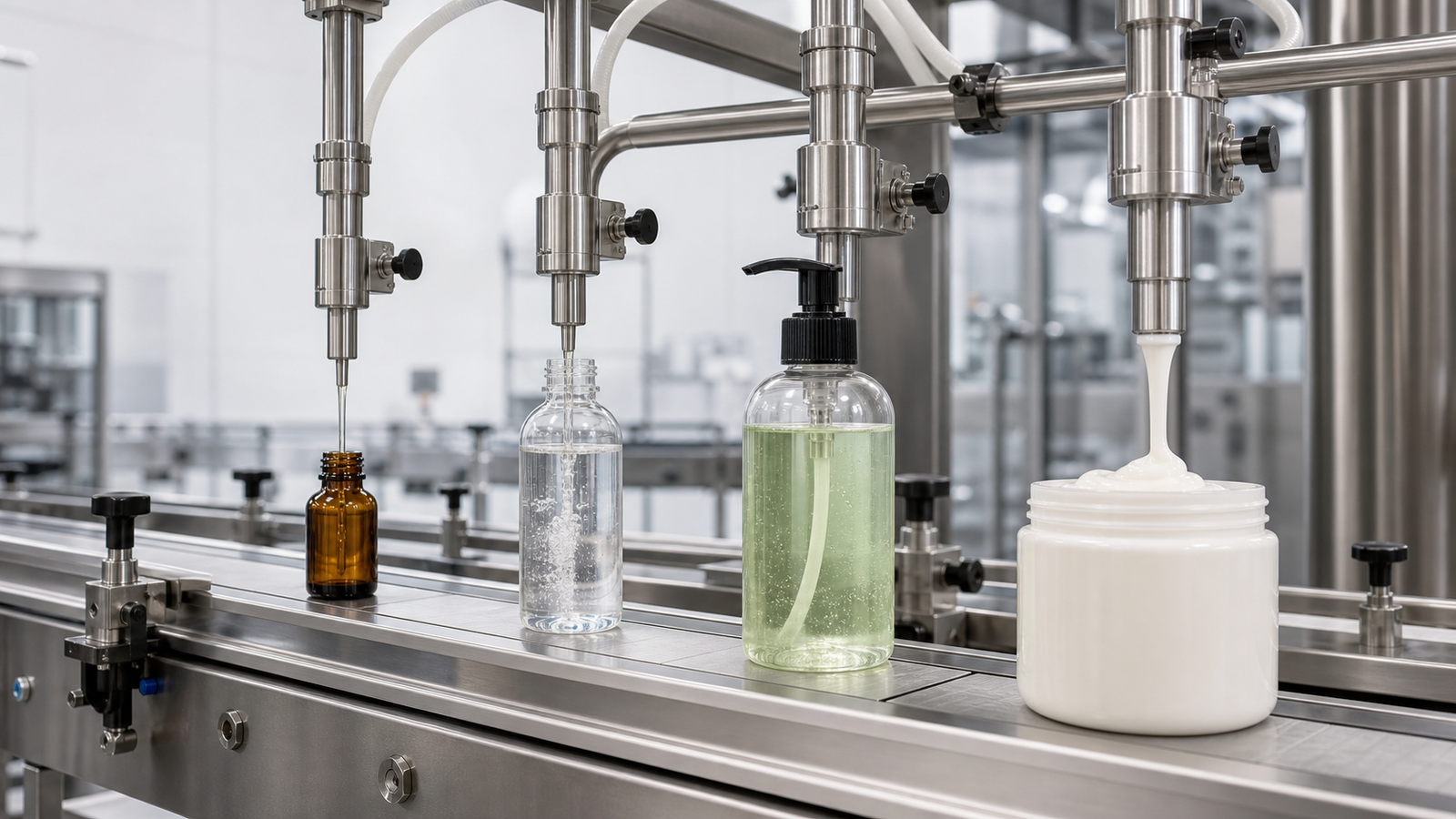
Quick answer: the six inputs that determine filler selection
Start with the product, not the machine. Record its viscosity across the actual operating temperature range, whether it contains particles, whether it foams or strings, its chemical compatibility and any hygiene or hazardous-area requirements. Then define the minimum and maximum fill volume, container and neck dimensions, closure, acceptable fill tolerance, required bottles per minute and the planned cleaning method.
Use a piston or other positive-displacement system for many viscous products and products with compatible soft particulates; use peristaltic filling when a disposable product path and small, clean doses are priorities; use magnetic, gear or other pump systems for compatible free-flowing liquids; use net-weight filling when mass control, density variation or product value matters; and consider overflow filling when a uniform visible fill level is more important than dispensing an exact measured volume. These are starting rules, not final specifications. A trial using the real product, container and closure should confirm the choice.
One-screen liquid filling machine selection matrix
| Product and packaging condition | Practical starting technology | Why it is often considered | Main questions to test |
|---|---|---|---|
| Water-like, non-foaming liquid; repeatable bottles | Timed-flow, flowmeter or compatible pump filler | Simple flow path and good scalability | Does supply pressure remain stable? Is the liquid conductive if an electromagnetic meter is considered? |
| Low-volume, clean liquid; frequent product-path change | Peristaltic filler | Product contacts the tubing, supporting rapid path replacement | Can the tubing tolerate the product and required service life? Does pulsation affect the target dose? |
| Medium- to high-viscosity cream, gel, paste or sauce | Piston or positive-displacement filler | Moves a defined displacement and can generate useful suction and discharge force | Does the product contain air, strings or particles? What valve and nozzle geometry is required? |
| Density changes with temperature or formulation; high-value product | Net-weight filler | Measures mass directly rather than inferring it from volume | Is the container stable on the load cell? What settling time is required? |
| Clear bottles where shelf appearance requires the same level | Overflow filler | Returns excess product and creates a consistent visual level | Can the product recirculate without foaming, aeration or quality loss? |
| Solvent, corrosive or reactive liquid | Chemically compatible, appropriately rated filling system | Material selection and area classification become primary design constraints | Which wetted materials, seals, enclosure ratings and ventilation controls are required? |
| Product with suspended pieces | Large-port piston or another particle-compatible metering path | Reduces shearing and blockage when correctly sized | What are the maximum particle size, concentration, fragility and distribution? |
This matrix is a screening tool. The final decision must also account for dose range, temperature, cleaning, container handling and line integration.
1. Classify the product before comparing machines
Viscosity is a range, not a single brochure number
Ask for viscosity at the temperature seen at the filler. A lotion that flows easily at 45°C may behave very differently after cooling in a day tank or hose. Many sauces, gels and cosmetics are also non-Newtonian: their apparent viscosity changes with shear. A single value measured under unspecified conditions is therefore not enough to size a pump, hose, valve and nozzle.
For an RFQ, provide:
- Viscosity or flow-test data at the lowest and highest filling temperature.
- Whether the product becomes thinner under pumping or thicker after standing.
- Product supply temperature and the acceptable temperature band at the nozzle.
- Hose length, elevation change and whether the source tank is pressurized.
- Whether the product strings, drips, splashes or traps air.
The nozzle is as important as the metering device. A diving nozzle may reduce splashing or foam by filling closer to the rising liquid level. A shut-off or suck-back design may control drips from stringy products. The correct geometry should be selected through a product trial rather than assumed from viscosity alone.
Foam changes the real cycle time
Foam can occupy bottle headspace, interfere with level sensing and contaminate the neck before capping. Slowing only the pump often reduces output without solving the root cause. A better evaluation considers bottom-up filling, multi-stage speed profiles, nozzle diameter, product drop distance, tank agitation and recirculation.
During trials, record the time from the start of filling until the bottle can leave without overflow. That total is the usable fill cycle. A supplier’s dry-cycle speed is not the same as stable output with a foaming formulation.
Particulates require a full flow-path review
Do not specify a machine by saying only that the product “contains pieces.” Provide the maximum particle dimension, normal distribution, concentration and whether the pieces may be cut. Check every restriction: tank outlet, hose, pump chamber, valve, nozzle and any screen. A large nozzle cannot compensate for a narrow valve upstream.
Fragile fruit pieces and abrasive suspensions create different problems. The first may require gentle handling and low shear; the second may accelerate wear. The trial should inspect particle integrity as well as dose consistency.
Chemical behavior can override every other selection factor
For acids, alkalis, solvents, oxidizers and aggressive cleaners, give the supplier the current safety data sheet and a written material-compatibility requirement. Review metals, plastics, tubing, elastomers, adhesives and lubricants in the wetted path. “Stainless steel construction” is not a complete compatibility specification.
If flammable vapor may create a classified area, the site owner and qualified safety or electrical professionals must determine the classification. In the United States, OSHA 29 CFR 1910.307 requires equipment and wiring in hazardous classified locations to be intrinsically safe, approved for the location or otherwise demonstrated safe for the hazard. The machine specification should therefore identify the actual class, division or zone and material group rather than using the vague phrase “explosion-proof.”
2. Choose the metering system from product behavior
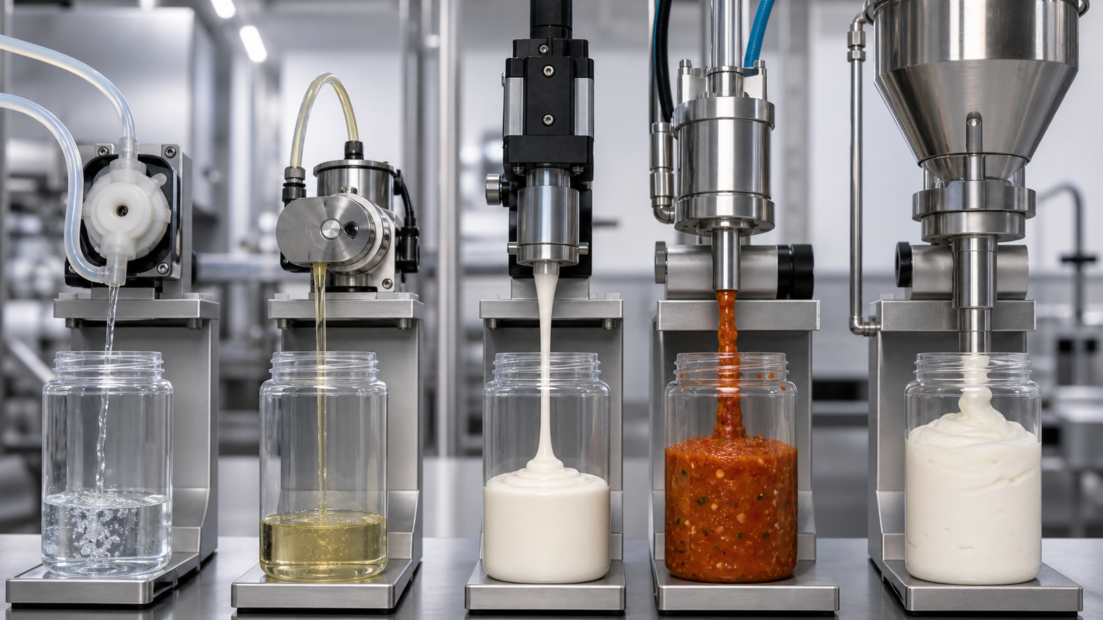
Piston filling
A piston draws product into a cylinder and discharges a set displacement. It is a strong candidate for creams, gels, sauces and other viscous products. Valve selection determines whether the machine can handle particles, stringing or rapid cleaning. Piston systems can cover a useful volume range, but very wide ranges may require different cylinder sizes or change parts to maintain practical resolution and cycle time.
Ask how the piston, seals and rotary or check valves are removed, cleaned and inspected. Also check how the system expels trapped air after cleaning or product changeover; air in the chamber can create underfills even when the stroke setting is unchanged.
Peristaltic filling
A peristaltic pump compresses flexible tubing to move liquid. Because the product can remain inside the tubing, this method is attractive for small doses, clean changeovers and applications where replacing the fluid path is preferable to cleaning a complex pump. Its suitability depends on tubing compatibility, tubing fatigue, required dose, speed and acceptable pulsation.
Treat tubing as a validated consumable. The RFQ should identify the tubing material, expected replacement rule, calibration method and how operators confirm that tube wear has not shifted the dose.
Magnetic, gear and other pump filling
Magnetic-drive and gear pumps can be compact and flexible for compatible liquids, but they are not interchangeable. A magnetic pump is often considered for clean, low-viscosity, non-particulate liquids when chemical compatibility is confirmed. Gear pumps provide positive displacement and can handle a broader viscosity range in suitable applications, but clearances, shear, wear and cleanability must be evaluated.
The practical question is not “Which pump is best?” It is “Which metering path gives stable flow with this formulation, at this temperature, through this hose and nozzle, while meeting the cleaning and changeover plan?”
Flowmeter filling
Flowmeters measure flow and stop at a target total. They reduce dependence on a dedicated measuring cylinder and can support recipe-driven changeovers. Meter type matters. Product conductivity, bubbles, viscosity, suspended solids, flow profile and cleaning chemistry all influence suitability. Confirm the meter’s measuring principle and installation requirements rather than accepting a generic “flowmeter filler” description.
Net-weight filling
Net-weight systems measure the container as product enters it. They are useful when the commercial requirement is mass, when density varies or when giveaway on large or valuable fills is costly. The tradeoff is that the container must remain stable on a load cell, and product motion or slow settling can extend the cycle.
Overflow filling
Overflow systems fill to a controlled level and return excess liquid. They are valuable when containers vary internally but must look level on the shelf. The recirculation path must be compatible with the product. Foaming, oxygen pickup, temperature change or contamination risk may make overflow filling unsuitable for some formulations.
3. Match fill range, accuracy and container size
Do not ask for one accuracy percentage without defining the test. Specify:
- Target fill values and the complete operating range.
- Whether acceptance is based on volume, mass or visible level.
- Sample size and sampling method.
- Product temperature, supply level and line speed during the test.
- Whether results are individual-container limits, average limits or both.
- Test instruments, resolution and calibration status.
- Stabilization time after startup, changeover or replenishment.
A machine can repeat a mechanical stroke while actual fill changes because of temperature, trapped air, foaming, supply pressure or product settling. Accuracy therefore belongs to the whole process, not only the controller.
If one machine must fill from a few milliliters to several liters, ask whether one metering element can realistically cover the range. Multiple pumps, cylinders or nozzles may be more reliable than forcing a single setup to operate at both extremes.
4. Match the filler to the container and closure
Obtain dimensioned drawings and physical samples for every bottle, jar, vial or pouch. Key data include body diameter, height, neck finish, opening diameter, wall stiffness, center of gravity and manufacturing tolerances. Also provide the cap, plug, pump, dropper or other closure.
Lightweight or unstable bottles may require pucks, neck handling, star wheels or side belts. Wide containers may reduce the number of nozzles that fit across a linear machine. Small openings may restrict nozzle size and slow a viscous fill. Flexible containers can deform under nozzle contact or vacuum.
The filling and capping line should be evaluated as one handling system. Bottle spacing, fill height, neck cleanliness and discharge control all affect downstream capping. A faster filler adds little value if bottles arrive at the capper with foam or contaminated necks.
5. Set output from a complete cycle, not a headline rate
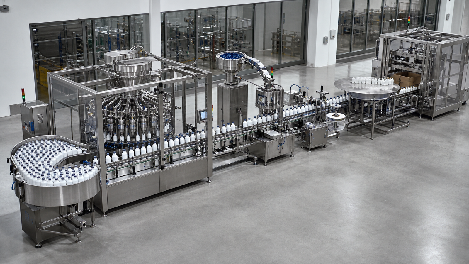
Start with saleable containers per shift. Then account for product changeovers, cleaning, replenishment, planned inspection, container jams and operator tasks. A simple planning relationship is:
Theoretical bottles per minute = number of active nozzles × 60 ÷ verified cycle time in seconds.
This is only a ceiling. The verified cycle must include bottle indexing, nozzle movement, filling, settling and discharge. Sustainable output is lower after real operating losses are included.
Ask the supplier to state the assumptions behind every speed figure:
- Product and temperature.
- Fill volume.
- Bottle and neck size.
- Number of nozzles.
- Foam-control profile.
- Upstream supply pressure or tank arrangement.
- Downstream capping and inspection capacity.
- Expected changeover scope.
For a growing factory, define today’s output and the 12- to 24-month requirement. A modular filler that accepts additional nozzles or integrates with automatic feeding, capping, labeling and inspection may be more economical than replacing an undersized machine.
6. Define hygiene, CIP/SIP and material requirements
Hygienic design must be translated into observable requirements. For food applications, 21 CFR 117.40 requires equipment to be adequately cleanable and maintained, food-contact surfaces to resist corrosion and withstand the intended product and cleaning environment, and automated systems to remain clean and sanitary. The 2026 update to the 3-A General Requirements Standard also emphasizes cleanable and inspectable seals and clearer requirements for CIP gasket joints.
Your user requirement specification should address:
- Product-contact materials and certificates required by the project.
- Surface finish where applicable.
- Drainability and dead-leg control.
- Tool-free or documented disassembly.
- Access to valves, seals and nozzles for inspection.
- CIP flow path, flow velocity basis, return monitoring and drain points.
- SIP temperature, exposure and condensate handling where sterile service is required.
- Prevention of cross-contact between formulations or allergens.
- Protection of open containers before closure.
Requirements differ by sector. A pharmaceutical filling project may prioritize controlled product paths, batch records and validation. A cosmetic filling project may prioritize rapid changeover across viscosities and packaging styles. A food filling project must connect product handling with sanitation and allergen controls. A chemical filling project may put compatibility, containment and classified-area design first.
7. Plan line integration and controls early
Define the upstream and downstream interfaces before approving the filler. The scope may include bottle unscrambling, rinsing, cap feeding, capping, induction sealing, labeling, checkweighing, rejection and case packing.
At minimum, agree on:
- Conveyor height, direction and usable space.
- Line-control philosophy and start/stop interlocks.
- “No bottle, no fill” logic and missing-container behavior.
- Product low-level, pressure and temperature alarms.
- Reject confirmation and reject-bin management where inspection is used.
- Recipe permissions and change history.
- Data required for batch records or production reporting.
- Recovery behavior after an emergency stop or power interruption.
Do not leave utilities until the end. Confirm electrical supply, compressed air quality and demand, water, steam, drainage, ventilation and product-transfer connections.
8. Use real samples and written FAT acceptance criteria
The factory acceptance test should reproduce the most difficult operating points, not only the easiest bottle and fill. Include the smallest and largest dose, lowest and highest viscosity condition, most unstable container, foamiest product and fastest planned output where practical.
| FAT test | Evidence to record | Example acceptance logic |
|---|---|---|
| Fill performance | Individual results, average, product temperature, speed and instrument ID | Meets the purchaser’s written mass or volume limits across the agreed sample |
| Drip, string and foam control | Neck photos, reject count and settling time | No product on the sealing surface and no overflow during normal transport |
| Container handling | Video at infeed, fill and discharge | No scuffing, tipping, deformation or recurring jams |
| Changeover | Tools, parts, settings and elapsed time | Completed by trained operators within the agreed procedure |
| Cleaning access | Disassembly demonstration and inspection points | All defined product-contact parts are reachable, drainable and accounted for |
| Alarm and interlock challenge | Alarm list with pass/fail result | Each critical alarm creates the agreed machine response and recovery state |
| Line communication | Interface-signal test | Upstream and downstream stops do not cause uncontrolled filling or bottle accumulation |
| Documentation review | Manuals, drawings, parts list and certificates | Required documents are present at the agreed revision level |
Water testing is useful for basic commissioning but cannot prove performance with a viscous, foaming, particulate or chemically aggressive product. When shipping the real formulation is impossible, agree on a justified surrogate and repeat critical confirmation during site acceptance.
9. Understand price drivers before comparing quotations
Quotation totals often differ because the scopes differ. Major cost drivers include the metering technology, number of nozzles, automation level, container change parts, cap feeding, servo controls, hygienic construction, CIP/SIP, hazardous-area protection, inspection, data integration, documentation and validation support.
Compare quotations with a scope matrix rather than a single total:
- Product and container range included.
- Guaranteed output and the stated assumptions.
- Acceptance test and product-trial scope.
- Change parts and spare parts included.
- Cleaning and material documentation.
- Upstream and downstream interfaces.
- Installation, training and commissioning.
- Warranty, remote support and service response.
The lowest purchase price can become the highest operating cost if changeovers are slow, consumables are proprietary, cleaning is difficult or the machine cannot expand with demand.
10. Prepare a complete RFQ for a tailored filling line
A useful RFQ includes the product data sheet and safety data sheet where relevant, viscosity versus temperature, particle details, foam behavior, fill range, tolerance definition, container and closure drawings, samples, target output, shift pattern, cleaning method, utilities, site layout and required standards.
King Pack can use this information to plan an integrated filling and capping line, select a metering path and create a trial-fill and FAT plan. The productive next step is not a generic price request. It is a sample-based engineering review that makes the assumptions visible before equipment is built.
For a broad introduction to the equipment category, see what you should know about liquid filling machines. This guide is the selection-focused pillar: it converts product, package and output data into a testable machine specification.
Frequently asked questions
What information is needed to select a liquid filling machine?
Provide the product’s viscosity and temperature range, foam and particle behavior, chemical properties, fill-volume range, container and closure samples, acceptable fill limits, target output, cleaning method, utilities and required standards.
Which liquid filler is best for high-viscosity products?
A piston or another positive-displacement system is often the first candidate, but the valve, nozzle, hose and product supply must also suit the formulation. Confirm the choice with the real product at the lowest expected filling temperature.
Can one machine fill both water-like liquids and thick creams?
Sometimes, but a very broad product range may require different pumps, hoses, cylinders or nozzle sets. Compare changeover effort, cleaning risk and performance at both extremes before choosing a universal configuration.
How many filling nozzles do I need?
Nozzle count depends on verified cycle time, target bottles per minute, container width and available machine length. Calculate from the slowest real product and largest planned dose, then confirm that the capper and conveyor can accept the output.
Is volumetric or net-weight filling more accurate?
Neither is universally more accurate. Net-weight filling measures mass directly and tolerates density variation, while volumetric systems can be fast and repeatable for stable products. Accuracy must be defined with a test method and verified under operating conditions.
What causes inconsistent fill volume?
Common causes include trapped air, changing product temperature, unstable supply pressure, worn tubing or seals, foam, inconsistent particles, nozzle dripping, poor calibration and insufficient settling time.
Do I need CIP or removable product-contact parts?
Choose based on the formulation, batch frequency, contamination risk and site sanitation strategy. CIP can reduce manual handling but must have a validated flow path. Removable parts may be simpler for small batches if disassembly, cleaning and reassembly are controlled.
How should I compare filling machine quotations?
Compare included product and package ranges, output assumptions, acceptance criteria, change parts, cleaning design, controls, inspection, documentation, commissioning and lifetime consumables. Do not compare price or maximum speed alone.
