 Skip to content
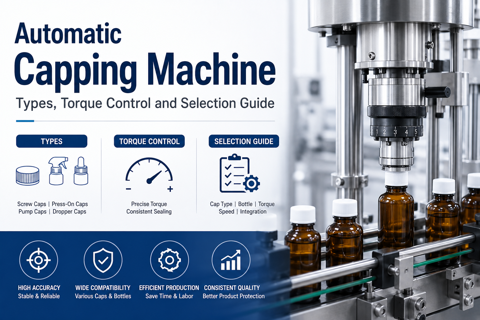
An automatic capping machine must do more than tighten a cap. It has to receive closures in the correct orientation, present each one consistently, stabilize containers, apply the intended torque, pressure or crimp, and transfer finished packs without scuffing or tipping them. The right automatic capper is therefore selected as a complete packaging process rather than as an isolated machine.
The best choice depends on the closure and neck finish, container stability, cap-feeding method, target speed, required changeover time, inspection strategy and upstream or downstream equipment. This guide compares the main technologies and explains how to turn those inputs into a practical specification for bottles, jars and vials.
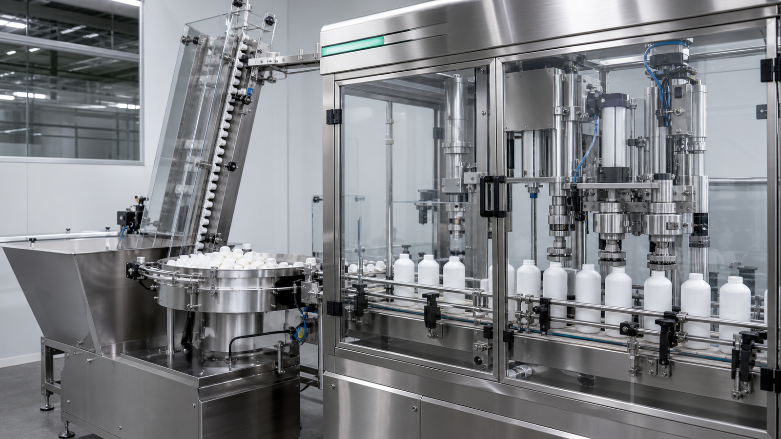
Quick answer: which automatic capping machine should you choose?
- Choose a spindle capper for many continuous-thread screw caps when flexible inline operation and fast size change are priorities.
- Choose a chuck capper when the cap must be engaged by a dedicated head and controlled during an indexed or rotary tightening cycle.
- Choose a servo chuck capper when recipe-based motion, tighter process monitoring and head-by-head data are important.
- Choose a press-on capper for snap-on, push-on or similar closures that are seated by controlled vertical force.
- Choose a ROPP capper for roll-on pilfer-proof aluminum closures whose threads and tamper band are formed around the container finish.
- Choose a crimp capper for closures such as vial seals, certain pump assemblies or aerosol components that require a controlled mechanical crimp.
- Choose a vacuum or twist-off capping system for compatible lug closures and hot-filled or vacuum-packed jars, after validating the complete container-closure process.
These are selection starting points. The actual decision should be verified with production containers, closures and product because friction, dimensional variation, liner behavior, neck support and contamination can change results.
Automatic capping machine comparison table
| Capping method | Typical closure or application | Main strength | Important limitation to validate |
|---|---|---|---|
| Inline spindle | Continuous-thread plastic or metal screw caps | Continuous flow, broad bottle-size flexibility and relatively quick mechanical changeover | Container side belts, cap placement and spindle settings must remain stable at line speed |
| Chuck | Screw caps, specialty closures and applications needing positive head engagement | Dedicated chuck can grip and drive the closure through a defined cycle | Chucks and change parts must match the cap; indexed motion may limit speed on a single-head machine |
| Servo chuck or rotary turret | High-speed or closely monitored screw-cap applications | Programmable motion, recipe control and improved process data | Higher capital cost and more demanding tooling, controls and maintenance |
| Press-on | Snap caps, plugs and push-on closures | Direct, controlled seating force | Excess force may deform the container; insufficient support can cause poor seating |
| ROPP | Aluminum roll-on pilfer-proof closures | Forms a secure threaded closure and tamper-evident band | Roller geometry, bottle finish and head setup are closure-specific |
| Crimp | Vial seals, some pumps, perfume collars or aerosol components | Forms the closure mechanically around a neck or ferrule | Crimp diameter, skirt appearance and component dimensions require close control |
| Vacuum or twist-off | Lug caps on compatible jars | Supports closure application where vacuum performance is part of the package | Product temperature, headspace, cap compound and jar finish all affect performance |
How an automatic capper works
Most automatic capping systems perform five linked functions. First, containers arrive with controlled spacing. A timing screw, star wheel, gating cylinder or servo conveyor separates and positions them. Second, a sorter or elevator orients caps and sends them to a chute, track or pick-and-place unit. Third, the cap is placed on or presented to the container. Fourth, the machine tightens, presses, rolls or crimps the closure while belts, guides, neck grippers or pockets stabilize the container. Finally, inspection devices check selected attributes and reject nonconforming packs.
Failures that appear to be a torque problem often begin earlier. A cap that is tilted in the chute, a bottle that rotates between side belts or an unstable container pitch can produce loose, cross-threaded or damaged closures even when the capping head is correctly set. The specification should therefore describe the complete path from bulk caps to accepted finished containers.
1. Match the capping method to the closure
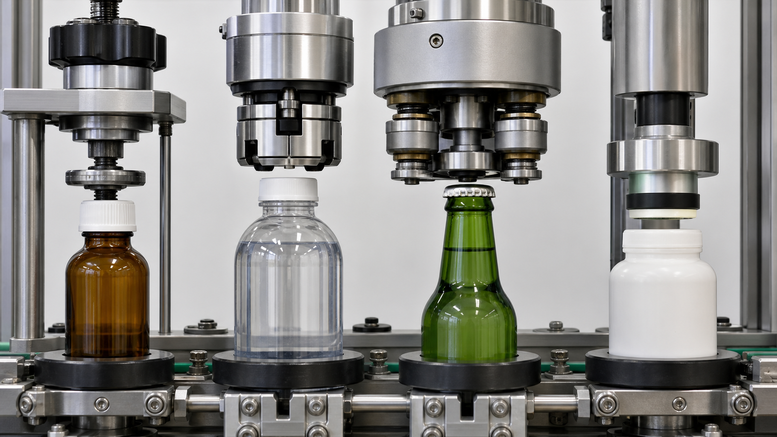
Spindle capping for flexible inline lines
An inline spindle capping machine typically uses opposing rotating wheels or belts to tighten a screw cap as the container moves continuously. It is widely considered for household chemicals, foods, cosmetics and other products using continuous-thread closures. Adjustable side belts keep the bottle from rotating, while successive spindle pairs apply increasing engagement and final torque.
The principal benefit is flexibility: many bottle heights and cap diameters can be accommodated without a full turret changeover. However, performance depends on consistent cap placement, adequate straight-wall contact for the stabilizing belts and sufficient conveyor control. Highly tapered, flexible or very small containers may require additional handling tests.
Chuck capping for positive engagement
A chuck capper encloses or grips the cap with a shaped head. The container may stop under a single head, index through multiple heads or travel around a rotary turret. Chuck systems suit applications where the closure benefits from more positive engagement than spindle wheels provide.
Mechanical clutch, pneumatic or servo-controlled heads can be used. The chuck insert must match the closure profile without marking decorative caps. If multiple closure sizes are planned, the quotation should state which chucks, inserts, guide parts and recipes are included and how long a verified changeover takes.
Press-on capping for snap closures
Press-on systems seat the closure using a belt, roller, platen or controlled head. The force must be high enough to pass the closure bead or locking feature but not so high that it collapses a lightweight bottle or damages the product. Neck support, base support and container material are key. A transparent inspection station can help confirm full seating around the entire circumference rather than on only one side.
ROPP capping for aluminum closures
A ROPP head uses rollers to form an aluminum closure around the container finish. Thread rollers form the cap thread and tucking rollers form the tamper-evident band. Correct setup depends on the closure specification, glass or plastic neck finish, roller profile, head pressure and vertical position. A result that looks acceptable from one angle may still have an incomplete bridge, skirt wrinkle or inconsistent release, so dimensional and functional tests should be included in the validation plan.
Crimp capping for vials and specialty components
Crimp cappers mechanically form metal or plastic around a ferrule, flange or neck. Pharmaceutical vials, perfume pumps and other specialty packs can require very different tooling, despite all being described as “crimped.” Define the components, target finished dimensions, acceptable cosmetic condition and inspection method. For sterile or controlled environments, also define material, cleaning and containment requirements before the head design is finalized.
2. Specify cap sorting, feeding and placement
The capper cannot outperform its feeding system. Common feeding methods include vibratory bowls, centrifugal sorters, step elevators and vision-guided or robotic pick-and-place systems. The correct option depends on cap geometry, softness, decorative surfaces, output and the number of formats.
A cap-feeding trial should answer practical questions: Can nested caps separate? Can a hinged lid open in the sorter? Will a soft liner fall out? Does a long dip tube tangle? Can a painted or metallized cap tolerate contact with the bowl? How often must an operator replenish caps, and can the bulk hopper be accessed safely?
The chute or track should control orientation without excessive back pressure. Sensors should detect low cap supply, jams and missing caps, while the machine control should stop or reject containers predictably. If caps arrive from a third-party supplier, test more than one lot so the equipment is not tuned to an unusually uniform sample.
3. Understand application torque and removal torque
Cap torque control is central to screw-capping performance, but “torque” must be defined carefully. Application torque is the force applied during capping. Removal torque is the force later required to open the closure. They are related but not identical. Liner compression, thread friction, product contamination, storage time, temperature and material relaxation can change removal torque after the package leaves the capper.
There is no universal torque value that is correct for every cap of a given diameter. The closure and container suppliers should provide a starting range, and the pack owner should validate it against leakage, seal integrity, opening force and distribution conditions. ASTM D2063/D2063M provides a recognized test method for measuring torque retention of continuous-thread closures, but a complete package specification may require additional leak, vacuum, pressure, induction-seal or transport tests.
For a multi-head machine, take representative samples from every capping head. A good overall average can hide one head that regularly over-tightens and another that under-tightens. Record the head number, time, product and component lot. Trend the results rather than reacting only to a single reading.
Torque-control technologies
- Mechanical clutch heads are familiar and economical, but require routine inspection and repeatable adjustment.
- Magnetic clutch heads can provide stable, contact-free torque transfer within their intended range.
- Pneumatic heads use regulated air and must be protected from supply-pressure variation.
- Servo capping heads can control motion and capture process data, but the measured motor value is not automatically identical to the package’s laboratory removal torque.
Whatever technology is chosen, the control system should protect approved recipes, identify permitted adjustments and show alarms clearly. Operators should not need trial-and-error changes to compensate for worn inserts, contaminated caps or unstable bottles.
4. Stabilize the container before increasing speed
Tall, narrow, flexible and irregular containers need more support than a rigid cylindrical bottle. Side belts, neck guides, star wheels, pockets and base plates can prevent spinning or tipping. Containers with handles or off-center necks may also require orientation before capping.
When evaluating samples, include the lightest empty container, the heaviest filled container and the least stable geometry. Test realistic fill levels because liquid motion can shift the center of gravity. For foaming or splash-prone products, confirm that the transfer from the filling and capping line does not contaminate the neck finish before the closure is applied.
5. Match capper speed to the whole line
Machine speed should be stated as sustainable accepted output, not only maximum mechanical cycles per minute. Upstream filler discharge, conveyor accumulation, cap replenishment, inspection time and downstream labeling or cartoning can all become constraints.
Define at least three values in the request for quotation: normal production rate, short-term peak rate and minimum controlled rate. Then identify the format on which each rate must be achieved. A capper that reaches the target with a large round bottle may not do so with a small unstable vial or a closure that requires long head engagement.
Useful line controls include blocked-and-starved logic, controlled ramping, accumulation sensors and communication of machine states. If the capper is integrated into a monoblock, ask how rejected containers are handled and whether a fault in the capping section affects filled but uncapped product.
6. Plan changeovers around parts, settings and proof
“Tool-free changeover” can mean different things. Some adjustments may use handwheels while chucks, star wheels or cap tracks still require format parts. Ask the supplier to divide the changeover into four categories: parts replaced, positions adjusted, recipes selected and quality checks completed.
A useful changeover package includes clearly identified format parts, scales or digital position indicators, stored recipes, photographs or work instructions and a master sample. During the factory acceptance test, have the intended operators perform a full changeover without coaching beyond the approved procedure. Measure the time from the last good container of one format to the first verified good container of the next.
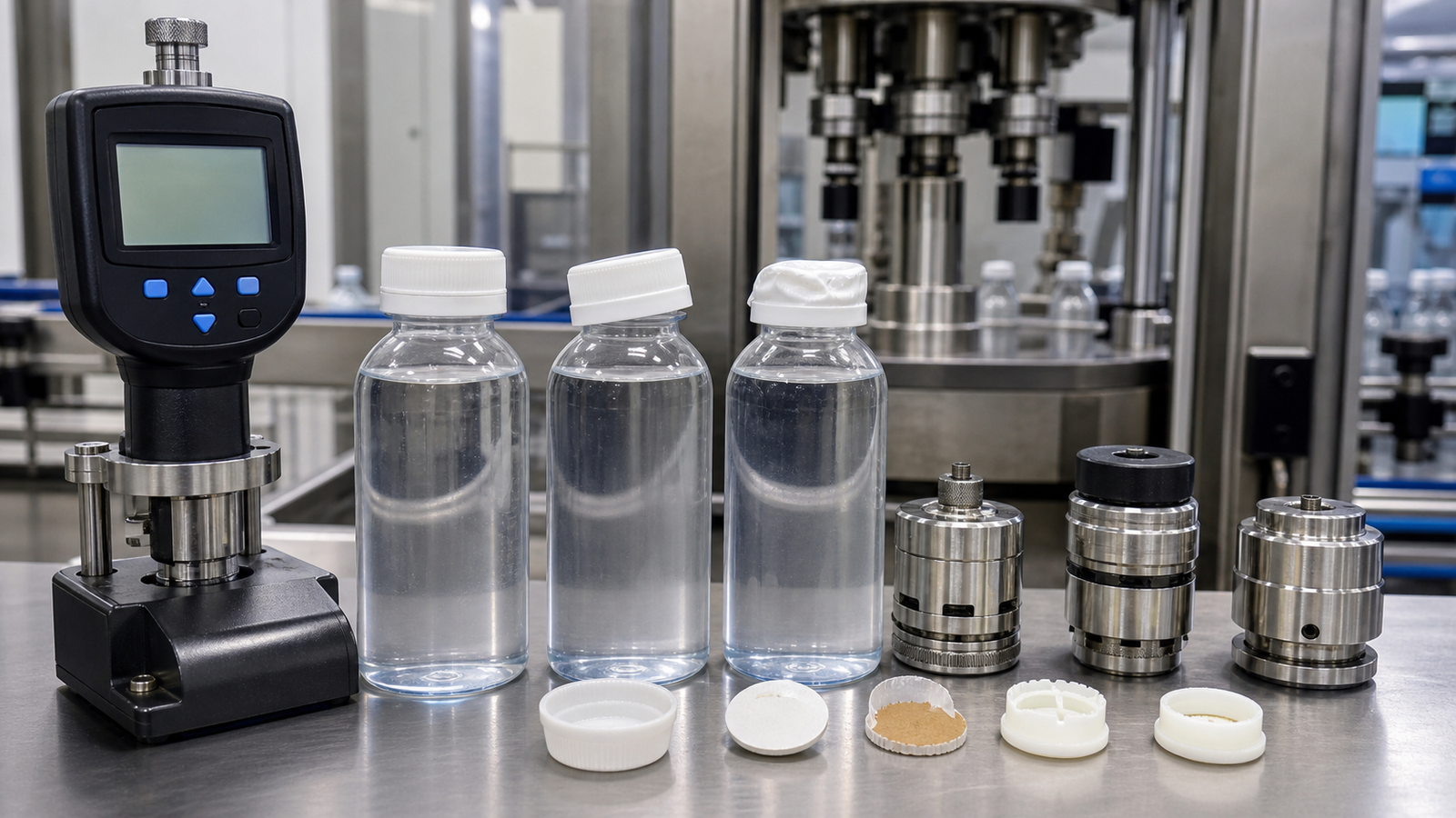
7. Diagnose common capping defects systematically
| Defect | Likely process areas to inspect | Practical checks |
|---|---|---|
| Missing cap | Low cap level, track jam, sensor timing, placement mechanism | Confirm cap-present detection and reject challenge; examine cap back pressure |
| Cross-threaded or tilted cap | Cap presentation, bottle pitch, neck finish, head alignment | Slow the machine for observation; compare container and cap dimensions across lots |
| Loose cap | Insufficient application, bottle spinning, worn chuck or liner variation | Sample every head; check stabilizing belts and head engagement time |
| Over-tight cap or damaged thread | Excess setting, hard head contact, wrong recipe | Verify approved setting and tooling; inspect container and cap threads |
| Scuffed decorative cap | Abrasive guide contact, unsuitable chuck insert, excess pressure | Mark contact points and test softer compatible inserts or gentler feeding |
| Incomplete ROPP or crimp | Roller or jaw position, head pressure, component dimensions | Measure finished geometry and inspect the full circumference |
| Wide torque variation | Component friction, product on threads, unstable air or worn heads | Separate results by head, component lot and time; correct the upstream cause |
Adjustment should follow evidence. The existing King Pack guide to capping-machine adjustment methods is a useful troubleshooting companion; this page remains focused on selecting and specifying the complete capping process.
8. Define hygiene, safety and validation requirements
For pharmaceutical packaging, the closure system must protect the product from foreseeable external factors and must not be reactive, additive or absorptive in a way that changes product safety, identity, strength, quality or purity. U.S. 21 CFR 211.94 also addresses cleaning and, where indicated, sterilization of drug-product containers and closures. Those package requirements should be translated into machine features such as cleanable product-zone surfaces, controlled component handling and documented procedures.
Projects for the pharmaceutical industry may require stainless-steel construction, low-particle mechanisms, restricted access barrier integration, data records and formal qualification support. Cosmetic packaging may place greater emphasis on preventing marks on premium caps, handling pumps or collars and changing among many decorative formats. Requirements vary by site and product, so state the applicable standard and acceptance evidence rather than relying on a generic “GMP design” label.
Safety design should address guarded moving parts, interlocked access doors, safe cap loading, lockout points and controlled recovery after a jam. Ask what happens to a container inside the machine during a stop and how an operator removes it without entering an unexpected motion zone.
9. Build a useful factory acceptance test
The factory acceptance test should reproduce the intended process closely enough to reveal handling and quality risks. Supply production-representative caps, containers and, when safe and practical, product or an agreed substitute with comparable behavior.
| FAT item | Evidence to record |
|---|---|
| Format coverage | Each agreed container and closure runs with listed change parts and recipes |
| Sustainable output | Accepted containers per minute over an agreed duration, including normal replenishment |
| Closure quality | Application or removal torque, seating, crimp or ROPP dimensions, visual condition and leak-related checks |
| Head consistency | Results identified by individual head or station |
| Fault challenges | Missing cap, fallen container, cap jam, open guard and downstream blockage detected and handled correctly |
| Changeover | Actual time, parts, settings and first-good-container verification |
| Documentation | Drawings, manuals, electrical records, parts list, calibration information and training materials reviewed |
Agree on the sampling plan, instruments, calibration status and acceptance limits before the test. Otherwise, both parties may arrive with different definitions of “good capping.” Any deviation should have an owner, corrective action and retest requirement.
10. Prepare an RFQ that produces comparable quotations
Send suppliers a structured package rather than only a target speed. Include:
- Dimensioned drawings and physical samples for every container, closure, liner and neck finish.
- Product characteristics that can affect the neck or closure, including splash, oil, solvent or powder residue.
- Normal, peak and minimum line rates for each format.
- Required torque, seating, crimp or roll-on acceptance criteria and the test method.
- Cap-loading preference, hopper capacity and operator access constraints.
- Available conveyor height, line direction, accumulation and communication signals.
- Environment, cleaning, electrical, air, documentation and validation requirements.
- Changeover target, spare parts, training, FAT, installation and service scope.
Price is influenced by head count, sorter complexity, servo controls, inspection, reject tracking, format parts, enclosure level and validation documentation. Compare the quoted scope line by line. A lower base price can become more expensive if essential cap tooling, container handling or acceptance testing is excluded.
Automatic capping machine selection checklist
Before approving a design, confirm that the answer to each question is documented:
- Has the supplier tested all planned containers and closures, including dimensional extremes?
- Is the capping method appropriate for the exact closure rather than only its nominal diameter?
- Can the feeder orient caps without scuffing, nesting or liner loss?
- How are unstable containers supported, and what prevents bottle rotation?
- How is application controlled and how will finished closure quality be measured?
- Can results be associated with individual heads or stations?
- Is the stated speed sustainable with normal cap replenishment and adjacent machines?
- Which change parts, tools, recipes and verification steps are required?
- What inspections and rejects are included, and how are rejected packs contained?
- Are cleaning, guarding, documentation, training and lifecycle service in scope?
Frequently asked questions
What is the difference between a spindle capper and a chuck capper?
A spindle capper tightens screw caps between rotating wheel sets while containers generally remain in continuous motion. A chuck capper grips each cap with a shaped head during an indexed or rotary cycle. Spindle systems are often selected for flexible inline formats; chuck systems offer positive cap engagement and can support closely controlled or specialty applications.
Does an automatic capper control removal torque directly?
Usually it controls an application mechanism or a related motor, clutch, pressure or motion value. Removal torque is measured on the finished package and can change with time, temperature, liner compression and material relaxation. Validate the relationship for the actual container-closure system.
What torque should be used for a bottle cap?
There is no safe universal value based only on cap diameter. Start with closure and container supplier guidance, then validate against leakage, seal performance, opening force, storage and distribution conditions. State the measurement method and timing with the acceptance range.
How can capping torque variation be reduced?
Stabilize bottles, keep the neck finish clean, maintain the feeder and capping heads, control air or servo recipes, and sample every head. Separate results by component lot and station so dimensional variation is not mistaken for a machine-setting problem.
Can one capping machine handle screw caps, pumps and trigger sprayers?
Sometimes, but the feeding and placement requirements can be very different. Long dip tubes and asymmetric triggers often require manual placement or specialized robotic handling before automatic tightening. The supplier should test each format and list the dedicated change parts and achievable output.
How fast is an automatic capping machine?
Speed ranges from modest indexed output to several hundred containers per minute on multi-head rotary systems. The meaningful figure is sustainable accepted output for the specified format, including feeding, inspection and normal production interruptions.
Which inspections should be included after capping?
Common checks include cap presence, cap height or skew, tamper-band presence, code or color, and container position. Torque, seal integrity or crimp dimensions may require sampled destructive or offline tests. Define how failed containers are rejected and verified.
What information does King Pack need to recommend a capper?
Provide container and closure drawings, samples, photos or video, product characteristics, target output, acceptable closure criteria, planned line layout, utilities, changeover expectations and the applicable industry requirements. King Pack can then assess whether an inline, indexed, rotary or integrated filling and capping line is the practical starting point.
From samples to a validated capping specification
The strongest capping project begins with real components and measurable acceptance criteria. Choose the technology that matches the closure, then verify cap feeding, container control, application quality, line balance and changeover as one system. A witnessed trial and a well-defined FAT reveal far more than a catalogue speed claim.
To discuss an automatic capping machine, send King Pack your container and closure samples, required output and quality criteria. The project team can review the format range and propose a capping or integrated filling-capping configuration for further testing.
