 Skip to content

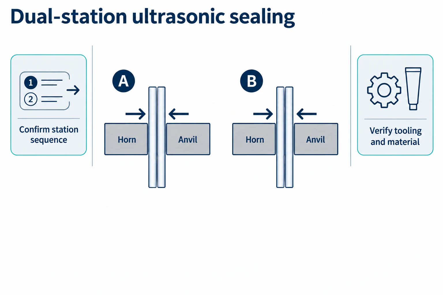
Dual-station ultrasonic tube sealing uses two coordinated sealing positions to close compatible thermoplastic tube tails. It can support parallel production or a compact layout when a project needs more sealing capacity than one station can provide. The result depends on tube construction, horn and anvil geometry, contact pressure, energy control, indexing accuracy and the cleanliness of the open tail.
This guide explains how to evaluate the process before purchasing equipment. It focuses on parameters that can be tested, evidence that should be recorded during factory testing, and installation details that influence the first production run. The process description assumes the correct orientation: the tube is filled through its open tail, then indexed to the ultrasonic sealing station. A sealed tube is never filled again.
When dual-station ultrasonic sealing makes sense
Two stations can be useful when a product line has a stable thermoplastic tube format and the sealing cycle limits the overall output. They may also help a contract manufacturer run two lanes of the same product or balance a filler with a downstream closure process. The machine should be evaluated as a complete sequence including tube loading, filling, tail presentation, sealing, coding, trimming and discharge.
Material compatibility comes first
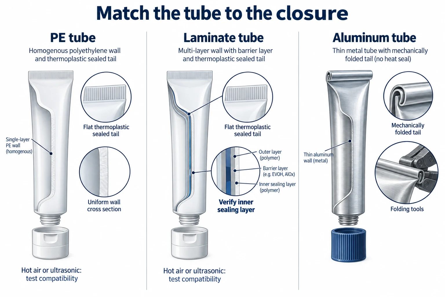
Ultrasonic energy is transferred through the tool interface and produces localized heat in compatible thermoplastic layers. PE and some laminate structures may be suitable, but compatibility depends on the actual layers, thickness and seal design. Aluminum tubes and structures without a suitable thermoplastic seal layer require a different closure concept. Request a material drawing and representative samples before approving the horn.
How the dual-station process works
Empty tubes are loaded into holders with the open tail facing upward. The dosing nozzle fills through the unsealed tail. The tube then indexes to the first or second ultrasonic position, where the horn and anvil close the tail under controlled pressure and energy. Downstream operations may include embossing, trimming, coding and discharge.
Station timing
Both stations need consistent indexing and contact timing. If one station reaches the tube before it is centered, the seal profile can vary. Review the transfer pitch, dwell time, horn stroke, pressure build-up and release delay. The controls should identify a missing tube or a station that has not returned to its home position.
Horn and anvil alignment
The horn should contact the specified seal area evenly. The anvil supports the opposite side and defines the seal profile. A small alignment error can create an incomplete seal, a thin edge or an excessive mark on the decoration. Ask how alignment is checked during setup and which parts are protected from product residue.
Parameters that need a defined window
Amplitude and energy
Amplitude affects how much vibration is delivered at the interface. Energy or weld time controls how long the material is exposed to the process. The correct setting depends on the tube construction and seal design. A supplier should record the approved range rather than provide one unexplained number. Use a controlled trial to find a stable window with acceptable appearance and integrity.
Pressure and hold time
Contact pressure must be high enough to create the intended bond but controlled enough to avoid damaging the tube or squeezing product into the tail. Hold time allows the material to stabilize before the horn releases. Check the effect of pressure and hold time on both station positions and on tubes from different production lots.
Tube tail preparation
The tail must be open, clean and correctly positioned. Product remaining in the seal area can create a weak seal or visible contamination. The nozzle cut-off, lift motion and tail alignment should be reviewed together. If the product is stringy, use a controlled cut-off and inspect the first samples after start-up.
Inspection and quality control
Visual inspection should check seal width, wrinkles, burn marks, incomplete closure, decoration damage and code position. A suitable integrity test may be added according to the package risk. The method should be agreed before FAT and should identify whether failures come from material, alignment, product contamination or parameter drift.
Sampling both stations
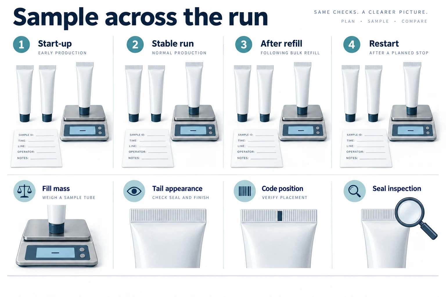
Do not approve the process from station one only. Collect samples from both stations at start-up, stable production, after a pause and after a setting change. Record the station identity, tube lot, recipe, energy, pressure and hold time. A side-by-side sample review makes differences easier to detect.
Integration with filling and coding
The ultrasonic unit must match the filler’s indexing and the coding system’s timing. If coding occurs after sealing, the code location should be checked against the final tail profile. If trimming or embossing is included, ensure that the tool does not distort the sealed area. The line should reject a tube that misses the filling step or fails a position check.
Cleaning and maintenance
Ultrasonic tooling should be protected from product build-up. Define how the horn and anvil are inspected, cleaned and reinstalled. Do not use an abrasive method that changes the contact profile. Include fasteners, shims and alignment references in the maintenance instructions. Keep approved spare horns or wear parts identified by part number.
Changeover between tube sizes
A format change may require a new holder, guide, horn, anvil or recipe. Store the parts in a labeled kit and include a first-piece check. Confirm tube diameter, tail width, seal length and decoration position before the run begins. The operator should see the active format and approved energy window on the control interface.
Factory acceptance test
Plan the FAT with representative tubes and a product or substitute that has similar flow behavior. Verify open-tail filling, tube positioning, both ultrasonic stations, seal appearance, code position, reject handling, changeover and cleaning access. If the actual formula is unavailable, mark the result as a substitute trial and identify which checks must be repeated at site.
Keep a parameter sheet with tube material, layer structure, horn part number, amplitude, energy, pressure, hold time and sample results. Record a photograph of the approved seal. This evidence helps the installation team reproduce the process after shipment.
Shipment inspection and installation preparation
Before dispatch, inspect the frame, guards, electrical cabinet, horn and anvil kits, spare parts and manuals. Confirm the destination power, air supply, floor access, ventilation and operator space. Protect the horn and anvil during transport and verify that the alignment references are included in the handover file.
Procurement checklist
- What exact tube layers and seal profile were tested?
- Are both stations independently adjustable and monitored?
- What are the approved amplitude, energy, pressure and hold-time windows?
- How are product-contaminated tails detected and rejected?
- Which tooling changes are required for each tube size?
- What inspection method will be used at FAT and site acceptance?
Discuss your requirements: Send your tube drawing, laminate structure, seal profile and target output to King Pack for an ultrasonic compatibility review and trial plan.
Compare the proposed station and tooling scope with the tube filling and sealing equipment overview; suitability still depends on the actual product and tube samples.
Product and tube trials
The best parameter window is found with the real interaction between product, tube and tool. A thick cream may leave residue in the tail, while a lower-viscosity gel may move during indexing. Prepare enough material to observe start-up, stable running and recovery after a stop. Use the same product temperature and storage condition expected during production. If a substitute is required, document its flow behavior and the limits of the result.
Tube-lot variation
Run samples from more than one tube lot when possible. Small differences in laminate thickness, tail width or surface finish can change the energy response. Record the supplier, lot and drawing revision. The purpose is not to create an artificial worst case, but to confirm that the approved settings have reasonable tolerance.
Control logic and reject handling
The line should prevent a bad sequence from becoming a sealed product. A tube that is missing, tilted, unfilled or out of position should be identified before the ultrasonic cycle. The control logic should also detect a station that has not returned home, insufficient air or a horn fault. Ask how rejects are removed and how the operator confirms that the affected piece cannot re-enter the good-product flow.
Restart after interruption
Define the restart sequence after a power, air or material interruption. The machine may need to clear tubes from the sealing station, clean a contaminated tail and repeat a first-piece approval. The procedure should state which settings are retained and which checks are repeated. This is especially useful for plants with several shifts or mixed operator experience.
Maintenance and service planning
Ultrasonic systems require regular inspection of the horn face, anvil, fasteners, guides and sensors. The maintenance file should explain how to identify wear, how to protect the contact surface and how to reinstall parts without losing alignment. Keep a record of service dates, parameter changes and replaced components. This information helps distinguish a material change from tool wear during troubleshooting.
Spare parts
Request a recommended spare-parts list for horns, anvils, gaskets, sensors, cables, fasteners and other wear items. Some parts may be format-specific. Store them in labeled kits with the approved drawing revision and installation orientation. A spare part without identification can create more downtime than it prevents.
Line layout and operator safety
Leave enough access around both stations for cleaning, inspection and safe tool changes. Guarding should prevent contact with moving or vibrating components while allowing controlled maintenance access. Mark the operator side, product flow, electrical isolation point and compressed-air isolation point on the layout. Confirm noise and vibration considerations with the site team when the equipment is installed near other work areas.
How to compare proposals
Compare proposals using the same specification sheet. Separate confirmed test evidence from assumptions, optional features and customer-supplied items. Check whether the quoted output includes both stations running, whether it assumes a particular tube material, and whether changeover time includes cleaning and first-piece approval. Ask for the limits of the proposal so the purchasing team can make a controlled decision.
Review support after delivery as well. Confirm training scope, remote assistance, spare-part identification, documentation language and the method for handling a failed site trial. A practical support plan is part of process reliability.
Recommended approval sequence
- Share tube drawings, product behavior and target output.
- Confirm that the tube contains compatible thermoplastic layers.
- Agree horn, anvil, seal profile and inspection method.
- Run both stations during a documented factory trial.
- Approve samples, parameter sheet and FAT record.
- Complete shipment inspection and installation preparation.
- Repeat first-piece checks during site commissioning.
Following this sequence gives engineering, quality and purchasing one shared reference. It also prevents a dual-station machine from being approved on the basis of a single attractive sample made under undocumented settings.
For multi-market projects, add local electrical standards, operator-language requirements, spare-part lead times and code formats to the installation file. These details are easy to miss because they do not change the ultrasonic principle, but they affect commissioning and routine operation. Keep a signed copy of the approved parameter sheet with the machine documentation.
After site acceptance, keep several approved tubes from the trial as a reference set. Identify each sample by tube lot, product condition, station, recipe and date. The reference set helps quality staff compare later production and gives service engineers a clear baseline when a seal appearance changes.
Include training, spares and commissioning requirements in the equipment service and handover scope so the plant can prepare its own personnel and utilities.
Clarify what the two stations actually do
The phrase “dual station” can describe two parallel production positions, an alternating arrangement, or one loading position paired with one sealing position. Ask for a station diagram and timing chart. A two-position worktable does not necessarily contain two ultrasonic stacks, and one generator may be configured to serve tools differently from two independent generators.
Generator sharing and recipe control
Ask which station can weld at each point in the cycle, how recipes are assigned and what happens if one tool reports a fault. These answers determine the real production sequence and maintenance strategy. Do not assume that two visible fixtures provide simultaneous welding.
Dukane’s packaging technology overview describes ultrasonic systems built around a generator and acoustic tooling. It is a useful reference for the components to discuss with a supplier; it does not establish the performance of a particular King Pack configuration or tube laminate.
Tool contact and acceptable marking
A horn pattern can leave an intentional impression in the seal. Define which appearance is acceptable before the trial and distinguish that pattern from excessive thinning, cracking or decoration damage. Examine samples after normal handling as well as directly at discharge. Agree whether codes are formed in the tail or applied by a separate printer.
Keep film or tail specimens where the package owner requires them, but avoid treating a flat-film weld as complete proof for a cylindrical tube. Tube geometry, the side seam, fixture support and product condition can change contact. The final decision should use finished tubes from the intended process.
Purchasing a complete ultrasonic system
List the generator, converter, booster where applicable, horn, anvil, fixture, sensors and control interface in the quotation. Clarify what is standard and what is format-specific. Ask how a replacement tool is identified and how the site verifies its setup. These details are particularly useful when the customer expects to add a different tail width later.
Before shipment, preserve the approved tooling identity and recipe record. At installation, inspect tool seating and support before repeating the first-piece checks. Transport protection should prevent contact-surface damage rather than relying only on the machine’s outer crate.
Send your specifications: Use the King Pack technical enquiry form to share the product profile, tube drawings and the conditions you need verified.
If two stations share power or pneumatic resources, include that interaction in the trial. Test the normal alternating or simultaneous sequence defined by the design, then observe whether either position experiences a changed contact condition. Record the permitted sequence with the recipe so an operator cannot unknowingly apply settings developed for a different station arrangement.
Use the same inspection method on both positions and keep the results separately identifiable throughout acceptance.
Ultrasonic setup evidence matrix
| Element | Record |
|---|---|
| Material | Tube drawing and lot |
| Tools | Horn and anvil identity |
| Sequence | Station and generator arrangement |
| Recipe | Approved control settings |
| Inspection | Appearance and integrity method |
FAQ
Can ultrasonic sealing be used for every tube?
No. The tube must contain compatible thermoplastic layers and have a suitable tail design. Confirm the actual structure with samples.
Why use two ultrasonic stations?
Two stations can balance the line when sealing time limits output or when a compact parallel layout is required.
How do I keep both stations consistent?
Use balanced indexing, aligned horns and anvils, independent sample checks and a defined parameter window for each station.
Does ultrasonic sealing replace a leak test?
No. It can produce a strong seal, but the appropriate visual and integrity checks should still be defined for the package.
Do two fixtures mean two simultaneous welds?
No. Confirm the generator, tool arrangement and timing chart. Dual station can describe different sequences, so the actual operating cycle must be explained and tested.
Conclusion
Dual-station ultrasonic tube sealing should be selected from material compatibility, tool geometry, process parameters and inspection evidence. Validate the open-tail filling sequence, both sealing stations, changeover and installation requirements before approval.
Request a technical review: Contact King Pack with your tube samples and closure requirements. Request a technical review, factory trial plan and installation checklist.
