 Skip to content

How to Insert Plungers After Syringe Filling
AI Answer Snapshot
Plunger insertion after syringe filling should be designed around the actual syringe geometry, product volume, air sensitivity and closure sequence. A reliable process controls syringe support, plunger orientation, insertion force and travel, then verifies seating, product displacement and trapped air with a documented sample method. The correct settings must be established with representative product and packaging during factory testing.
Introduction
Plunger insertion is often treated as a simple downstream action after filling. In veterinary syringe production it is a product-quality and package-control step. The plunger must enter the barrel without damaging the syringe, pushing product out of the tip, trapping unacceptable air, or stopping short of the defined seating position. The correct process depends on product rheology, target fill, syringe tolerance, plunger material, flange geometry and the way the filled syringe is supported.
This article gives engineering, quality and procurement teams a practical method for specifying and validating a plunger insertion station. It describes the information to prepare for an RFQ, the checks to include in factory acceptance testing, and the installation details that should be ready before commissioning. It does not prescribe a universal insertion force, speed or tolerance. Those values must be established from the customer’s product, syringe and acceptance method.
1. Define the insertion sequence before selecting equipment
Start with a process map. Identify syringe loading, filling, nozzle withdrawal, product check, plunger feeding, plunger orientation, insertion, inspection, coding and discharge. State whether the syringe is supported at the flange, barrel, tip or a dedicated nest during each step. A plunger station cannot be evaluated separately from the transport and filling sequence because movement at one station can affect the next.
Describe the package in a specification: barrel material, internal diameter, barrel length, flange, tip geometry, plunger material, plunger seal profile, rod length and any printed or molded orientation feature. Provide drawings and samples from the intended packaging supplier. The drawing defines nominal dimensions; samples reveal tolerance, friction and surface conditions that influence insertion.
Information for an RFQ
• Product type, temperature range, viscosity behavior and air sensitivity.
• Target fill volume or mass and the agreed verification method.
• Syringe drawings, plunger drawings and representative samples.
• Required insertion sequence, cap or tip closure and downstream equipment.
• Format range, changeover frequency and cleaning restrictions.
• FAT evidence, operator training, documents and spare-parts expectations.
2. Understand why air control matters
When a plunger enters a filled syringe, it displaces a volume of air and product. If the insertion path is too fast or the product is sensitive to compression, air can become trapped, foam can appear, or product can be pushed through the tip. If the plunger starts at an angle, one seal lip may contact the barrel before the other and create uneven resistance. The machine should therefore control alignment, support and motion rather than simply push the plunger until a sensor changes state.
The acceptable air condition must be defined by the customer’s quality team. Some products can tolerate a small visible headspace; others need a defined appearance or functional check. Do not use a generic “air-free” claim. Record the inspection method, lighting, sample size and acceptance examples. A repeatable visual standard is often more useful than an unsupported numerical promise.
Trial conditions for air assessment
Test representative product at the intended preparation temperature. Include a start-up condition, a stable run and a restart after a planned pause. Record whether the syringe was fully supported, how the plunger was presented, and whether any manual intervention occurred. If a substitute product is used, label it clearly; a substitute can demonstrate machine motion but cannot prove final product air behavior.
3. Select a plunger presentation method
Plungers may be supplied in bulk, oriented by a feeder, presented in trays or loaded manually. The best method depends on package volume, format variation, labor model and the plunger’s geometry. Bulk feeding can support a repeatable automatic sequence when the plunger is robust and consistently oriented. Tray loading may be useful for delicate or high-variation components. Manual presentation can be appropriate during development or for a broad mix of low-volume formats.
Ask how the system detects missing, inverted or damaged plungers. A reject route should be defined before the machine is ordered. The station should also allow operators to clear a jam without exposing the product unnecessarily. The supplier should identify which contact parts and guides change for another plunger or syringe format.
4. Control alignment and insertion motion
The insertion head, nest and syringe support should be designed as one system. The nest should hold the barrel without marking or distorting it. The insertion head should maintain the plunger axis and accommodate the defined travel. If the plunger rod is flexible, a guide may be required. If the plunger has a keyed feature, orientation should be verified before contact.
Insertion speed and acceleration are engineering variables. A slower approach can help stabilize alignment; a controlled final movement can reduce sudden product displacement. These are conditional recommendations to test with the actual package. They should not be presented as guaranteed results. Record the selected profile in the recipe or FAT record so the customer can reproduce it after installation.
What to measure during a sample test
Measure or inspect plunger seating, visible air, product displacement, barrel damage, tip leakage, cap fit and final package dimensions. If insertion force is monitored, define how the signal is used and what action follows an out-of-range result. A force trace is useful only when the package and test method are stable enough to interpret it.
5. Handle product displacement and tip protection
The product volume and the remaining headspace determine how much the plunger will displace. If the syringe tip is open, the sequence may need a controlled tip orientation or a temporary protection method. If a cap is installed before insertion, verify that the cap and seal can tolerate the pressure and movement created by the plunger. If the tip is closed after insertion, include that operation in the process map.
Product on the tip or flange can affect sealing, coding and visual inspection. The machine should define where the product check occurs and how a contaminated syringe is rejected. The quality team should specify whether a wipe is allowed, because manual wiping can hide the actual process condition.
6. Cleaning and line clearance
Plunger insertion may not be a large product-contact station, but product can reach nests, guides and the tip support. Map the surfaces that can receive product during a start-up, a stop or a misaligned insertion. Define how those surfaces are inspected and cleaned. If several veterinary formulations use the same line, include changeover and line-clearance steps in the trial.
The cleaning method should be approved by the product owner. Do not select a chemical because it is convenient without checking compatibility with seals, plastics and coatings. The supplier can document accessible areas, removable guides and recommended spare parts; the customer approves the final production cleaning procedure.
7. FAT and shipment inspection
A factory acceptance test should use the final syringe and plunger whenever practical. Confirm loading, orientation, filling interface, plunger presentation, insertion, inspection, reject handling and downstream transfer. Define the sample quantity and the inspection method before the test starts. Include a planned stop and restart so the team can assess the first samples after interruption.
Record the machine configuration, tooling identification, product condition, recipe, operator interventions and open actions. If a different plunger lot is used, record the difference. Shipment inspection should compare the machine with the approved configuration and confirm that nests, guides, tooling, manuals, drawings, spare parts and packing records are present.
8. Installation preparation
Prepare floor space, service connections, compressed air, electrical supply, access for cleaning, operator reach and the connection to the next station. Keep the latest syringe and plunger drawings available to the commissioning team. The site should know which adjustments are operator-controlled and which require maintenance access.
Training should cover loading, plunger orientation, recipe selection, jam clearing, cleaning, line clearance and reject review. Quality staff should receive the sampling and inspection method. Maintenance staff should receive the part list and adjustment information. This division of responsibility supports a clear SAT and handover record.
9. Supplier evaluation checklist
Compare supplier responses line by line. Ask which syringe and plunger samples were reviewed, which format parts are included, how orientation is detected, how air and product displacement are inspected, what the FAT will prove, and which documents are delivered. Ask the supplier to label each statement as a confirmed capability, a conditional engineering proposal or an item requiring a sample test.
King Pack can review syringe drawings, product behavior, plunger requirements and line interfaces, then propose a configuration and FAT scope within the confirmed project requirements. Its confirmed support areas include syringe and veterinary filling solutions, custom configuration, factory acceptance testing, documentation, training and line integration.
10. Internal links and image references
Review the [veterinary filling solutions](https://kpfillingmachine.com/veterinary-filling-solutions/) page for application context, the [syringe filling machine](https://kpfillingmachine.com/syringe-filling-machine/) page for equipment categories, and the [FAT checklist](https://kpfillingmachine.com/fat/) page for acceptance planning.
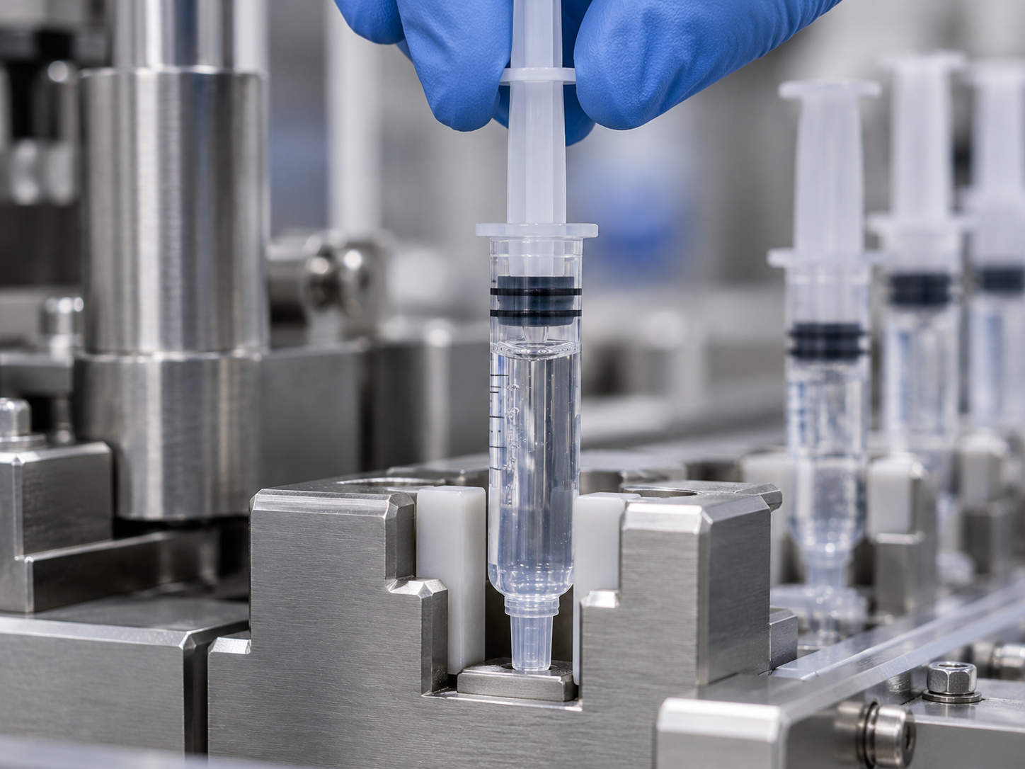
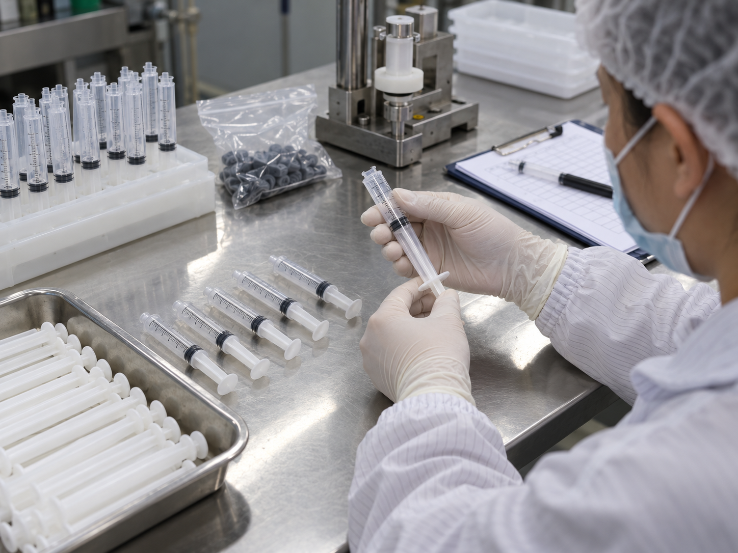
Image 1 caption: Plunger alignment and syringe support before insertion. Image 1 ALT: Veterinary syringe held in a support nest before controlled plunger insertion. Image 2 caption: Inspection of plunger seating and visible air after insertion. Image 2 ALT: Filled veterinary syringe checked for plunger seating and visible air. Image 3 caption: FAT review of plunger tooling, samples and inspection records. Image 3 ALT: Factory acceptance test review of veterinary syringe plunger tooling and samples.
FAQ
Can plunger insertion be added after filling later?
It may be possible, but the syringe support, transfer, controls and available space must be reviewed. Adding a station later can require new tooling and a revised acceptance test.
How do we prevent product from being pushed out of the tip?
Review headspace, plunger travel, insertion profile, tip orientation and closure sequence with representative product. The correct method must be confirmed during testing.
Is a force sensor mandatory?
Not always. Its usefulness depends on package variation, inspection strategy and the customer’s quality plan. A sensor should have a defined purpose and response.
What should FAT include?
FAT should cover the agreed product and package, plunger presentation, alignment, insertion, inspection, reject handling, restart condition, cleaning access and documents.
What should we send for a proposal?
Send product information, syringe and plunger drawings, samples, target fill, closure sequence, formats, cleaning method and site interfaces. CTA: Send Your Syringe and Plunger Specifications to request a technical review.
Conclusion
A reliable plunger insertion process is designed around the product, syringe, plunger and closure sequence together. Controlled alignment, support, motion and inspection reduce the risk of air, displacement and seating problems. CTA: Request a technical proposal and FAT plan based on your actual syringe samples and plunger requirements.
11. Build a repeatable acceptance record
The acceptance record should make the insertion result reproducible. Record the syringe and plunger lot, product identifier, product temperature, target fill, machine recipe, tooling reference and sampling plan. Include the first samples after start-up, samples from the stable run and samples after a planned pause. Photograph representative seating and air conditions using the same inspection approach that the quality team will use at the plant.
If a result is outside the agreed condition, record the observation before changing a setting. Note whether the issue was plunger orientation, barrel support, product preparation, tip leakage, a damaged component or a transfer problem. Change one variable at a time when practical and record the reason for the change. This creates evidence for the final setting instead of relying on an operator memory.
12. Plan for multiple veterinary formats
A project may begin with one intramammary syringe and later add another volume, plunger or cap. Treat each addition as a controlled format change. List the parts that change, the parts that remain common, the recipe parameters, the expected setup sequence and the checks required before release. This avoids assuming that a similar-looking package can use the same nest or insertion travel.
Format changes should also be considered in the layout. Leave access for removing nests and guides, provide a clean location for change parts, and label each set so that the operator can identify it during line clearance. Maintenance and quality teams should know how the format is confirmed before the first filled syringe is accepted.
13. CTA for a technical review
Send the product description, syringe drawings, plunger samples, target fill, closure sequence, planned formats and cleaning restrictions to King Pack. The engineering review can then define the insertion concept, sample-test method, FAT evidence and installation information required for your project. Ask for a written scope that separates confirmed capabilities, conditional recommendations and open items.
Before approving the line, ask how the machine reacts to an absent plunger, a reversed plunger, a damaged syringe and a jam at the insertion head. The answer should identify the sensor or operator check, the reject route and the safe recovery procedure. These details protect the product and reduce the chance that a temporary workaround becomes the normal process.
Also confirm the relationship between plunger insertion and final packaging. If the filled syringe goes to coding, cartoning or an applicator assembly, check the transfer height, orientation and buffer capacity. A good insertion station can still create a downstream problem if the package is released in the wrong direction or if the next station cannot accept the discharge pattern.
The following factory-style visuals illustrate the type of tooling, support and inspection discussed above. They are illustrative engineering references, not measured output or validation results.

For a project review, compare the syringe filling machine range, the veterinary medicine application, the intramammary syringe filling solution and the filling and capping line. Related planning resources include what a syringe filling machine does, automating syringe capping and plunger insertion, syringe format changeover, intramammary line validation, reducing syringe filling waste, selecting filling nozzles for viscous products, the product catalogue, the packaging solution overview, the contact page and the request-a-quote page. Send your syringe drawings, plunger samples, product information, target fill and inspection method for a technical review.
