 Skip to content


AI-generated illustration: diagnose package location and transfer stability at an indexing conveyor.
Introduction
An intramammary applicator may look like a simple plastic barrel, but it is not handled like a bottle. The body, flange, fine cannula, plunger and cap create an asymmetrical package with limited surfaces that can safely contact machine tooling. When that package travels between feeding, filling, closing, inspection and cartoning, small differences in support or timing can make it rotate, tip, scuff or miss the next station.
For a veterinary manufacturer, these events are more than minor line interruptions. A barrel that is not stable can change fill-nozzle alignment, place stress on a fine tip, confuse a presence sensor or create rejects downstream. The answer is not simply to make the conveyor faster or add more guide rails. A reliable route starts with the actual component geometry and traces every handoff through the line.
This guide explains how engineering, packaging and procurement teams can specify stable intramammary barrel handling. It addresses non-sterile veterinary applicator projects and should be read with the manufacturer’s own package drawings, quality criteria and trial plan.
The direct answer
An intramammary barrel remains stable when the line supports it at repeatable package datums, controls orientation before each critical station, protects the cannula from uncontrolled contact and uses transfer tooling that matches the real component tolerances. The correct fixture, star wheel, nest or walking-beam design should be demonstrated with representative barrel lots. Nominal dimensions alone do not prove that an applicator will index consistently in production.
Request a handling review
Send the barrel drawing, empty samples, cannula and closure components. We can identify the dimensions and transfer points that should be reviewed before a line layout is released.
Start with the barrel as a handling component
Line designers need more than the nominal fill volume. They need to know which surfaces can locate the barrel, how stiff the flange is, whether the body is tapered, how the tip projects and how much normal molding variation appears across supply lots. For example, a fixture that lightly locates a straight cylindrical body may not remain stable when the actual barrel has a taper, a flexible flange or a long cannula that shifts the center of mass.
Create a component brief containing the barrel drawing, material, critical tolerances, acceptable cosmetic-contact zones and the supply presentation. Clarify whether components arrive loose, in trays, magazines or nested holders. A feeder that works well with neatly oriented trays may need a different separation or orientation step for loose bulk components.
Identify the safe datums
A datum is the surface or feature used to position the barrel. It might be a flange, shoulder, barrel outer diameter or another defined feature. The selected datum should be stiff enough for repeatable location and outside any cosmetic or functional zone that must not be marked. A fine cannula should normally be protected, not used as an uncontrolled guide.
The project review should show each datum in the fixture drawings. It should also explain what happens if a barrel is outside its expected tolerance. Good design does not assume every incoming component is perfect. It guides an acceptable part consistently and sends an unacceptable part to a defined reject path rather than allowing it to damage equipment or move into the next process step.
Map every handoff, not only the fill station
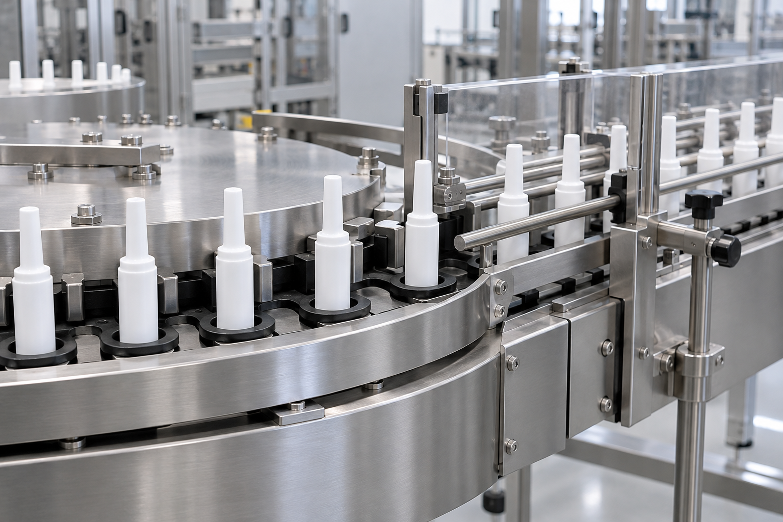
AI-generated illustration: Stable indexing depends on support and transfer control across the full handling route.
Many handling problems are introduced before the barrel reaches the filler. An applicator may separate correctly at infeed, then rotate during a transfer to an indexing dial. It may remain stable at filling but catch a guide during plunger insertion or discharge. The useful engineering exercise is a handoff map from incoming components to cartoning.
For each handoff, ask:
- Which feature supports and locates the barrel?
- Is orientation confirmed before the next critical operation?
- Can the cannula or cap contact a fixed guide unexpectedly?
- What clearance is allowed for normal component variation?
- Does the transfer create acceleration, vibration or a change in support direction?
- How is an incorrectly positioned barrel detected and removed?
This map is valuable during a factory acceptance test. Instead of watching only the finished applicator, the team can observe the stations where package control changes. Photos and short videos of these points make installation preparation clearer for an overseas project team.
Choose the handling route around the package
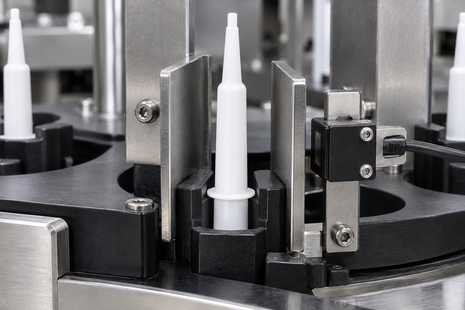
AI-generated illustration: The barrel support zone and protected tip clearance should be confirmed with representative components.
There is no universal best conveyor for intramammary applicators. An indexing dial can provide precise station-to-station presentation for certain formats. A walking beam may provide controlled transfer for another format. Nests, custom pockets, star wheels or guided belts may be used in different parts of a line. The correct solution depends on barrel geometry, component supply state, line sequence and agreed output requirements.
Indexing dials and nests
An indexing dial or nest system can hold a barrel at a defined position while filling, plunger insertion or closure operations take place. The engineering questions are how the barrel enters the nest, which surfaces touch it, how debris is prevented from affecting location and how the nest is changed for a different format. Review the true change-part scope rather than assuming similar barrel sizes share the same tooling.
Guided conveyors and transfer rails
Guided conveyors can be suitable when the package needs to move between modules, but guide rails must not become the primary control for a fine tip. The barrel should have positive, repeatable support while guides provide only the intended restraint. Too little control can permit rotation. Too much contact can create scuffing, drag or component stress. Factory trials should include enough samples to show whether the selected guide relationship remains stable over a realistic sequence.
Component tolerance is a production input
The component drawing describes the target. Incoming lots reveal the manufacturing range. A handling system should be evaluated with physical samples from the intended supply chain whenever possible. If multiple lots are available, use them in the sample trial. This gives the team a practical view of whether a fixture is robust or overly dependent on one ideal sample.
Do not turn a component issue into a vague machine complaint. When a barrel tilts or rotates, record the component lot, position, operating condition and station where the deviation appeared. Measure the relevant feature with packaging engineering support. The outcome may be a tooling adjustment, an infeed change, a component-specification clarification or a defined rejection limit. The evidence matters more than assigning blame quickly.
Use a representative factory trial
The trial should be designed to confirm the handling route, not merely produce a short video. Before the test, agree the component samples, route, operating sequence and observations. During the test, observe feeding, orientation, transfer, location at the critical stations, reject response and discharge. Where a line will use more than one barrel or closure format, identify what is and is not included in the trial configuration.
Useful observations include barrel stability at first start-up, after a controlled stop, through normal transfers and during any simulated out-of-position challenge. If a component cannot be tested at the factory, record it as a site-acceptance or customer qualification item. This avoids treating untested conditions as guaranteed performance.
Mid-article CTA — Send your component drawing
Share the barrel, plunger and cap samples with their intended supply state. We can prepare a handling review that identifies the locating datum, change parts and trial observations needed for your project.
Plan inspection around actual handling risks
Inspection is most useful when it is linked to a real risk. Depending on the project, a line may check component presence, barrel position, orientation, plunger position, cap presence or visible package condition. The manufacturer should define which result is acceptable and how rejects are segregated. The machine supplier can define sensors, cameras and mechanical stations, but acceptance criteria must be agreed before FAT.
For example, if a barrel can enter a station rotated from its intended orientation, decide whether a mechanical key prevents entry, a sensor detects it, a vision check confirms it or the line rejects it. The response must be repeatable and visible to operators. An alarm alone is not a complete reject strategy.
Prepare site installation around the verified route
After the trial and FAT, keep the handling evidence with the project records. The installation team should know the component presentation used at the factory, the fixtures installed, utilities required and the initial checks expected at site. Before shipment, inspect tooling protection, label change parts clearly and record the supplied component samples or drawing revision.
At site acceptance, reproduce the intended component feed condition as closely as practical. Confirm that the line is level, guide settings are correct, operators understand the changeover procedure and incoming components are controlled against the reviewed specification. A factory route is a useful starting point, but site performance still depends on local utilities, operator practice and actual component supply.
Make changeovers part of the stability specification
Stability is not proved only on a line that remains set for one format. When a project will run more than one barrel, the changeover procedure needs the same engineering attention as the initial fixture. List the parts that are format-specific: nests, rails, star wheels, locators, guide sets, sensors, recipes and any tooling that sets the presentation at filling or closing. A change-part list should state its part number, installation position and the component revision it was designed for.
After a changeover, operators should not have to infer correct alignment from a single finished applicator. The start-up check can include an empty-barrel observation through the relevant transfer points, a check that locating elements move freely and a documented first-piece inspection. Where adjustment is permitted, define the reference position and who is authorised to make it. This makes later troubleshooting more disciplined: a drift in handling can be compared with an agreed setup rather than a remembered machine setting.
It is also useful to discuss cleaning and access early. Product or environmental debris at a locating surface can affect the same features that control barrel position. The line layout should allow the customer to inspect and clean accessible tooling using its approved procedures. Cleaning responsibility and materials must remain with the customer’s process requirements, but the fixture design should not create inaccessible pockets that make routine observation impractical.
Turn observations into an evidence record
The most useful trial record is specific enough for the production and quality teams to use after the equipment ships. For each handling concern, record the component identity, the station, the observed effect, any adjustment and the result after the adjustment. A small evidence table can be more valuable than a general statement that the line “ran well.”
| Observation | Evidence to retain | Project decision |
|---|---|---|
| Barrel does not settle fully into a nest | Photos or video, barrel lot and nest reference | Review datum, clearance or incoming part tolerance |
| Cannula approaches a guide during transfer | Transfer-point image and guide setting | Confirm protection clearance and mechanical restraint |
| Position sensor gives an intermittent signal | Sensor position, component sample and operating condition | Check sensing method and define repeat trial |
| Changeover alters barrel presentation | Change-part IDs and first-piece records | Add a documented setup and verification step |
This type of record does not replace the customer’s validation documentation. It gives the teams a common factual starting point for FAT, installation preparation and future component-supply discussions. It also avoids an easy mistake: treating a change in a part lot as proof that a machine setting must be changed without first confirming the relevant dimension and route.
Questions procurement should resolve before ordering
Procurement teams can reduce later rework by obtaining the package information before final layout approval. Ask the component supplier for controlled drawings and the latest revision; identify whether cosmetic restrictions apply to flange, barrel or cannula areas; and define who owns the acceptance decision if a trial sample falls outside the expected range. If components will be bought regionally after the line is delivered, the supplier and change-control route should be visible in the project plan.
The request for quotation should also distinguish supplied equipment from customer-owned qualification work. A supplier can quote for change parts, handling stations, sample trials and agreed inspection functions. The product owner remains responsible for the approved product, component specifications, cleaning procedures, quality system and final release criteria. Clear ownership is not administrative detail: it tells each party what evidence must be available before shipment and site start-up.
FAQ
Why do intramammary barrels rotate on a conveyor?
Rotation can result from an unsuitable locating datum, insufficient support, excessive guide clearance, component variation, transfer acceleration or an infeed orientation issue. The right correction comes from observing the specific handoff where control is lost.
Can one line handle several intramammary barrel sizes?
Possibly, but each format needs a documented change-part and handling review. Similar nominal volumes do not guarantee the same flange, barrel, tip or closure geometry.
Should we send multiple component lots for testing?
Yes, when available. Multiple lots help show whether the proposed handling route is robust to normal incoming variation.
Does stable handling prove final product quality?
No. Stable handling is one part of a complete filling and packaging process. Product preparation, filling, closure assembly, inspection and the customer’s quality procedures must also be evaluated.
Can a changed incoming tray affect conveyor stability?
Yes. Incoming presentation can change how a barrel reaches its location feature even when the barrel itself is unchanged. Record the tray or holder revision and observe separation and transfer before adjusting the conveyor. This separates an input-presentation issue from a support or indexing issue.
Conclusion
Stable intramammary barrel handling is created by controlled support, real component evidence and a disciplined review of every transfer point. It should be specified as a package-engineering problem, not reduced to a conveyor-speed question. When the line uses the correct datums, protects the cannula and proves the route with representative components, the filling and closing stations begin with a much more reliable package position.
Discuss your applicator handling project
Contact Us: KINGPACK configures intramammary syringe filling lines around the actual barrel, plunger, cap and product route. Contact us with component drawings and samples to request a handling review, trial plan or quotation.
—
