


Introduction
An intramammary applicator filling project is not finished when the last cap is seated. The assembly still has to leave the supplied machine, cross a transfer interface and reach the next operation in a known condition. Buyers should specify that handover by defining the package state, orientation, support, transfer geometry, accumulation limits and route for units awaiting review. These decisions belong in the project layout and trial plan before equipment interfaces are finalised.
This guide concerns mechanical and operational handover of non-sterile veterinary intramammary applicators. It does not establish medicinal-product quality, cap retention, transport qualification or release criteria. Those assessments require the customer’s approved methods. The useful procurement question is narrower: how will a finished assembly move from the filling line to collection or cartoning without losing its intended presentation or inspection status?
Define the end of the supplied line
A quotation should identify the point at which the machine supplier’s responsibility ends. That point may be a discharge conveyor, a collection tray or an agreed interface to downstream equipment. “Ready for cartoning” is not sufficiently precise if the parties interpret the phrase differently.
Describe what crosses the boundary
Record the complete assembly expected at discharge: barrel format, plunger condition, cap state and orientation. Identify any inspection already completed and any checks still required downstream. A cap visible on the applicator does not itself prove functional retention, just as an assembly leaving the machine does not automatically establish release.
A useful handover statement connects the physical package with its process status. State whether discharge receives only assemblies accepted by the agreed equipment checks, whether trial samples can use the same route and where uncertain units are held. Confirm the actual supplied detection and rejection functions; do not assume that an automatic line identifies every possible defect.
Assign the downstream interface owner
If another supplier provides cartoning equipment, name the party coordinating the interface. Confirm who supplies the connecting guide, conveyor, controls and guarding where applicable. The boundary should remain clear during factory testing and installation preparation. Neither supplier should be expected to approve an interface it has not reviewed.
Map orientation through the transfer
The orientation needed for collection can differ from the orientation needed by a cartoner. Discuss whether the assembly arrives lying down, upright or held in a format-specific support. Then trace how that orientation is maintained or deliberately changed.
Protect the tip and closure
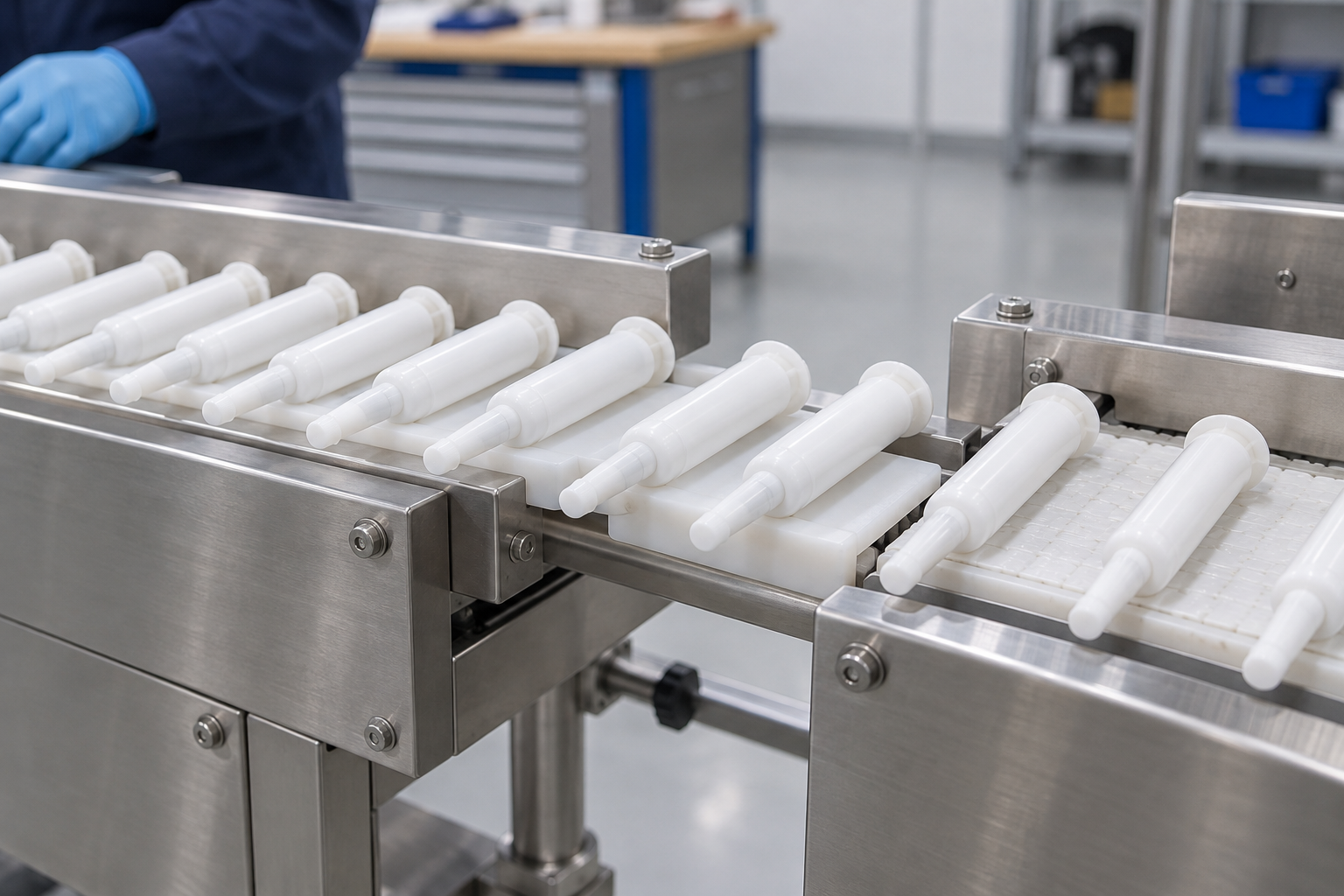
Identify surfaces that can receive guide or conveyor contact, using the actual package drawing and representative samples. A blunt fine dispensing tip is not a convenient universal stop or alignment feature. Review clearance around it and around the cap as the assembly changes support.
Also consider the plunger end and any protruding features. An applicator that rests stably on a straight section may rotate or catch where the next guide starts. Photograph the actual arrangement during an agreed trial and record the package condition before and after the handover. Do not interpret a short, carefully arranged run as proof of every incoming lot.
State the required orientation downstream
Ask the receiving equipment supplier which package feature controls its location. That requirement should be translated into the discharge interface rather than left for operators to correct repeatedly. Where a manual collection stage is intended, describe how operators preserve presentation without reaching into moving equipment.
This article owns discharge orientation after assembly. The separate component presentation guide owns the incoming state of barrels, plungers and caps before feeding. Keeping these boundaries explicit prevents two documents from trying to answer the same question.
Review the physical transfer geometry
Compare the actual discharge and receiving layouts. Identify the transfer height, available space, package support and any change in direction. Use controlled drawings and the supplied interface specification, not a generic height taken from an unrelated machine.
| Interface question | Evidence to prepare | Decision owner to confirm |
|---|---|---|
| What package state arrives? | assembly drawing and inspection-stage map | customer and filling-line supplier |
| How is it supported? | samples and contact-zone review | interface designer |
| What orientation is needed next? | downstream locating requirements | receiving-equipment supplier |
| What happens during a downstream stop? | proposed hold and recovery route | customer operations and integration owner |
| How are uncertain units separated? | agreed reject and material-status procedure | customer quality and operations |
Review gaps and changes in support
A transfer gap can expose a component to loss of support. The appropriate gap and guide arrangement depend on the actual assembly geometry and proposed mechanism. Do not publish or use a universal clearance value for all intramammary formats.
Observe the transition with identified samples. Look for rotation, catching, tip contact and changed cap position. Where an issue appears, preserve the initial condition before an authorised adjustment. Useful evidence identifies the component combination, tooling revision and location of the observation.
Check access as well as alignment
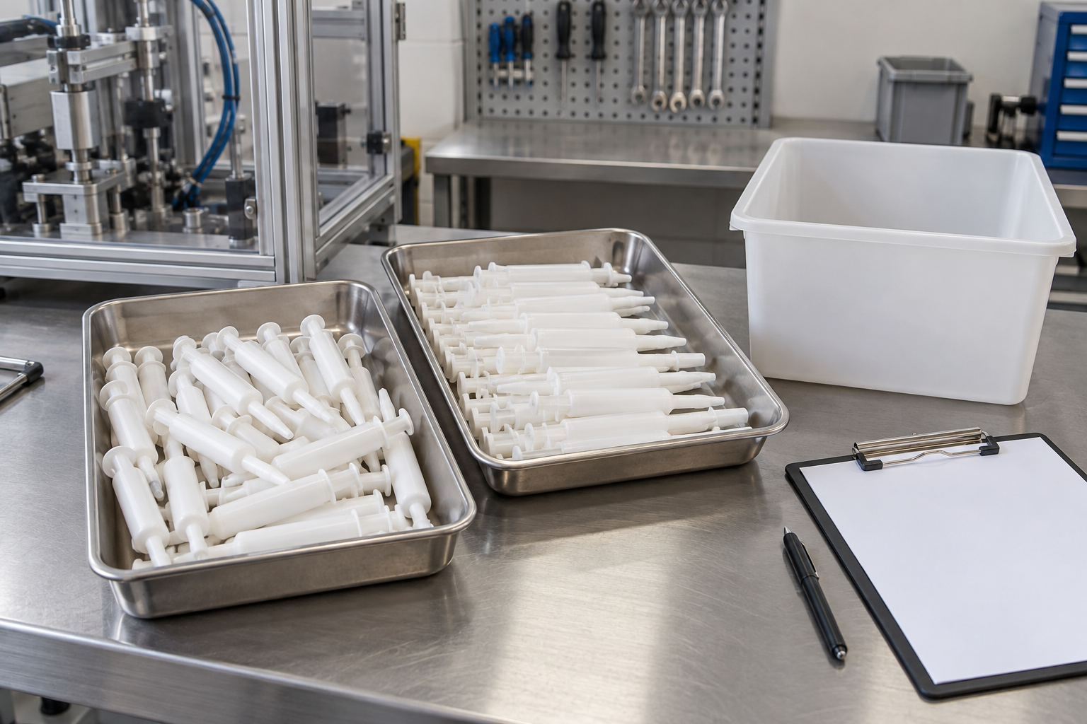
An interface must allow replenishment of collection containers, inspection and authorised intervention without obstructing required access. Discuss how the customer will remove a filled tray and where the next tray waits. Follow the machine instructions and site safety procedures for access and isolation.
A convenient collection arrangement can become unsuitable when it blocks a service door or puts containers inside an operator’s normal route. Review the surrounding work area during layout approval. The customer’s installed site, rather than a showroom arrangement, is the relevant context.
Define accumulation without assuming unlimited buffering
Accumulation is a project decision about how material waits when downstream flow changes. Ask whether the proposed route provides a controlled buffer, requires an upstream pause or uses manual collection. Confirm which features are included in the quoted scope.
Decide what happens when collection is full
Describe the event that requires intervention and how the operator is informed. State which action follows the supplied instructions. Do not assume the line can continue safely merely because packages can physically accumulate on a conveyor.
Crowding can change orientation and contact between assemblies. A planned trial can observe the agreed waiting state, but it should not create damaging situations simply to challenge the mechanism. The parties should agree a safe scenario, expected response and material disposition before testing.
Review downstream interruptions
When a cartoner or receiving conveyor stops, locate assemblies held on both sides of the boundary. Identify which team controls them and how the upstream line’s recovery relates to the downstream equipment. An upstream restart is not automatic authorisation to feed every retained unit onward.
Use the line stop and restart guide for the broader recovery map. The discharge specification should supply the interface details that map needs: waiting positions, package status and the point at which responsibility transfers.
Send Your Requirements: Share your applicator assembly drawing, proposed discharge layout and the next packaging operation. Ask for a review of the transfer boundary, sample inputs and integration questions.
Keep held and accepted assemblies distinguishable
A discharge route should not obscure the difference between accepted assemblies, trial samples and material awaiting a decision. The customer’s procedures should define the physical locations and records used for those categories. Equipment handling observations are not a substitute for that material-control system.
Identify the hold location before the trial
Agree where an uncertain assembly goes and who can authorise its next step. Choose a location that preserves identification and does not allow inadvertent return to the accepted flow. Where a hold container is used, include its placement in the review of the work area.
The example is a planning question, not a claim that every line contains an automatic hold diversion. Ask the supplier which routes are physically provided and which actions remain operator-owned. Document any manual step explicitly so it does not disappear from the final scope.
Connect exceptions to the relevant observation
If a transfer changes the visible package condition, identify the affected location and material rather than recording only a general stoppage. Include the component combination, the receiving arrangement and what happened before intervention. Refer cap-retention questions to the customer’s defined test method; a transfer photograph alone cannot establish retention.
Reconciliation records can help account for held units and samples removed for review. The separate component reconciliation guide owns the counting boundaries. The discharge article owns the physical hand-off that makes those boundaries understandable.
Plan representative factory observations
Before factory testing, agree which discharge arrangement can actually be assembled. The complete downstream machine may not be available at the filling-line supplier’s site. In that case, state the temporary receiving arrangement and the limits of the demonstration.
Start with the agreed assembly
Use identified barrel, plunger and cap combinations that represent the intended package. Record whether samples are empty assemblies, use an agreed simulant or contain customer-approved trial product. These conditions are not interchangeable evidence.
For a mechanical transfer question, empty assemblies can provide useful observations of location and orientation. They may not represent the complete product-filled package behaviour. The customer and suppliers should decide which further checks require the intended filled state and approved handling conditions.
Include ordinary operational transitions
Observe initial discharge, controlled waiting where included, container changes and a safe agreed recovery scenario. Record interventions and changes to the proposed interface. Trial quantities and acceptance criteria should be agreed for the specific question; this guide does not invent a standard sample size.
Photographs and a short station-by-station record should show what was demonstrated. Include unsuccessful observations and any revised condition. A report becomes less useful if it only preserves the final successful run and omits the adjustment needed to reach it.
Carry the interface into shipment and installation
During shipment inspection, check supplied transfer parts, guards, accessories and documentation against the agreed scope. Identify items supplied by another party and the interfaces the customer must complete. Shipment inspection confirms the stated delivery checks, not the final applicator’s distribution performance.
Prepare the installed receiving arrangement
Installation preparation should confirm the actual layout, collection containers, access and downstream connection. If the receiving equipment differs from the factory arrangement, document that change and review the affected transfer questions.
Do not compensate for an unexpected site mismatch by quietly altering the supplied layout. Seek the appropriate engineering review and preserve the revised arrangement in the handover record. The installed interface becomes the basis for later training and support.
Transfer operating responsibilities
Show operators where assemblies wait, how collection changes are performed and how an uncertain package is segregated. Distinguish routine actions from maintenance or quality decisions requiring separate authorisation. Keep the current instructions accessible near the operating workflow.
A useful handover makes responsibility concrete: who watches the receiving area, who requests a controlled pause, who clears an authorised obstruction and who decides the status of held material. Avoid relying on one commissioning attendee’s memory after the supplier leaves.
Build a concise discharge-interface evidence pack
Keep the assembly reference, approved layout, supplied interface scope, contact-zone notes, trial observations and remaining actions together. Identify which documents were updated after installation and which conditions are still provisional.
When an unexplained discharge issue recurs, compare the current component combination, collection arrangement and settings with that baseline. A changed downstream guide or container can affect the handover even when the filling machine has not changed. Record the observed difference before attributing the cause to the filler.
The evidence pack should make a supplier discussion specific. It should not become a collection of marketing photographs described as proof. AI illustrations, including those in this guide, explain the questions to review; only identified project evidence can support an acceptance decision.
Review downstream changes before reusing the interface
When the customer changes a collection container, cartoner infeed or transfer guide, compare the new condition with the approved discharge arrangement. The assembly may be unchanged while its supporting surfaces or waiting positions are different. Identify the affected interface instead of treating every downstream change as unrelated to the filling line.
Preserve the original and revised condition
Record the changed item, drawing reference and reason for the change. Review orientation, access, guarding and material-status control with the responsible parties. If a trial is needed, identify the package and configuration used. Keep the initial observation beside the revised result so a later team can understand what was actually changed.
Maintenance also deserves this check when a guide or support is replaced. Confirm that the replacement matches the supplied interface rather than relying on visual similarity. After an authorised adjustment, use the relevant package observations and the customer’s approved first-piece procedure before returning to routine flow.
FAQ
Can finished intramammary applicators discharge directly into any cartoner?
No. The receiving interface must match the complete assembly, required orientation, locating features and agreed flow-control arrangement. Review drawings and representative samples with the integration owner rather than assuming nominal package size establishes compatibility.
Does visible cap presence establish an acceptable discharge assembly?
It answers only a visible presence question at the stated observation point. Seating, functional retention and product-release requirements need their approved methods. Confirm which checks the supplied equipment performs and which decisions remain customer-owned.
State the temporary receiving arrangement and its limitations. Complete the checks that can be demonstrated meaningfully, then preserve the remaining installed-interface questions for the agreed site review. Do not claim full integration acceptance from an incomplete configuration.
Should all material held during a downstream stop continue afterward?
Only if its status and the approved recovery procedure permit it. Identify retained packages, segregate uncertain material and coordinate recovery across the equipment boundary. The decision should not depend solely on the fact that machine motion has resumed.
What information is useful for a discharge-layout review?
Send the complete assembly drawing, identified samples, filling-line discharge information, downstream locating requirements, proposed collection method and site layout. Mark provisional inputs and identify which party owns the connecting interface.
Conclusion
Intramammary applicator discharge handover joins package engineering with the customer’s next operation. A clear specification defines the assembly state, orientation, support, waiting conditions, hold route and responsibility boundary. Representative observations then show what the proposed interface demonstrated and what remains to be checked after installation.
Contact Us: KINGPACK can discuss discharge and packaging integration within a proposed intramammary filling-line scope. Send your applicator format, next operation and layout to prepare a focused technical review; final interface features and acceptance responsibilities should be confirmed for the project.
—