
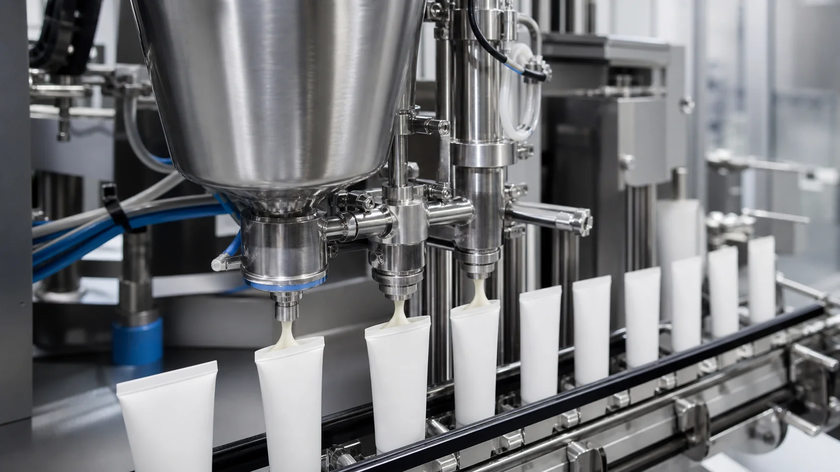
A cream tube filling machine can deliver the correct average weight and still produce unacceptable tubes. Strings on the nozzle, hidden air pockets, intermittent underfill, smearing and product in the seal zone usually come from an interaction among rheology, temperature, hopper condition, feed pressure, nozzle geometry, lift motion and cutoff timing. Changing one speed value without mapping that interaction often moves the defect instead of removing it.
Quick answer: stabilize the product before adjusting the filler. Confirm temperature, viscosity history, density and deaeration; maintain a flooded and repeatable pump inlet; then tune nozzle diameter, bottom-up motion, shutoff and suck-back using actual tube samples. Record each trial by defect, setting and result so the approved window can be transferred into a production recipe.
Quick defect-to-adjustment map
| Symptom | Likely contributors | First checks | Evidence to record |
|---|---|---|---|
| Stringing at cutoff | Nozzle too small, product too cold, slow shutoff, insufficient suck-back | Product temperature, tip condition, cutoff timing | Tail length, drip count and nozzle photo |
| Air pocket in tube | Aerated bulk, vortex in hopper, nozzle starts too high, lift too fast | Density, hopper level, nozzle start position | Sectioned tube or X-ray/weight evidence where available |
| Weight variation | Unstable inlet pressure, air in pump, worn valve/seal, inconsistent refill | Hopper level, pressure trend, pump repeatability | Sequential weight data and time stamp |
| Smearing on tube wall | Tube not centered, nozzle contact, poor dive profile | Holder fit, centering and nozzle runout | Slow-motion observation and marked samples |
| Product in seal zone | Overfill, stringing, tube squeezed in transport, fill level too high | Net fill, clean-tail margin, handling | Tail-zone photos before sealing |
| Splashing or satellites | Excessive discharge velocity, nozzle too high, product too warm | Fill speed, bore, temperature | High-speed video or controlled visual trial |
Treat rheology and temperature as machine inputs
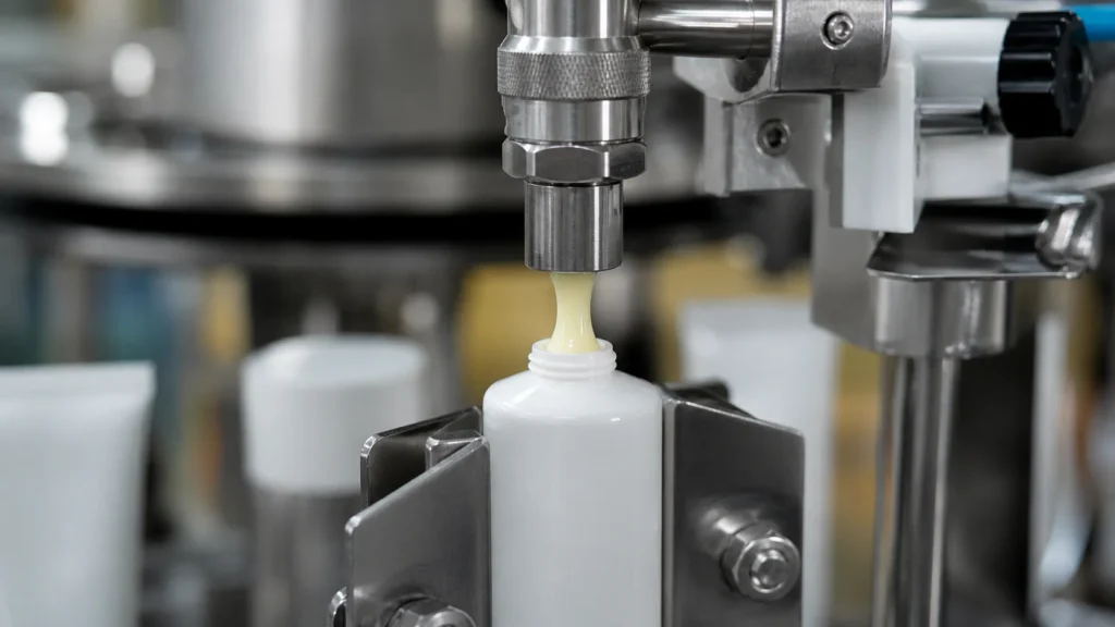
Creams and ointments are often non-Newtonian. Their apparent viscosity changes with shear, temperature and time after mixing. A single viscosity value without the measurement method does not describe how the product will flow through a hopper, pump and nozzle. Record spindle or geometry, speed, temperature, sample conditioning and time after manufacture.
Build a filling-temperature window rather than a single target. A warmer product may fill with less pressure but can splash or continue flowing after cutoff. A colder product can increase stringing, refill time and pressure variation. Test the planned beginning and end of the permitted window and include a realistic production hold.
The product history matters. A batch transferred through a high-shear pump may behave differently from a hand-carried laboratory sample. Slow agitation can maintain uniformity, yet excessive agitation or a surface vortex can introduce air. Define the transfer route, hold time and hopper agitation as part of the filling process.
For the broader relationship between viscosity and equipment configuration, use the high-viscosity tube filling engineering guide. This page focuses on defect diagnosis at the filling station.
Control hopper agitation and deaeration
The filler hopper should deliver a uniform, bubble-free product to the dosing unit. Verify that the inlet remains flooded across the normal level range and that a low-level condition stops the machine before the pump draws air. A narrow outlet, sharp transition or poorly placed agitator can create starvation even when the hopper appears full.
Use gentle agitation only when the formula needs it. The agitator should prevent separation or temperature gradients without making a vortex. Observe the product surface at maximum and minimum operating level. If air is drawn downward, reduce speed, change impeller position, add an appropriate anti-vortex feature or revise the level range.
Deaeration should occur upstream whenever possible. Vacuum mixing or a controlled post-mix vacuum stage can reduce entrained air, but the endpoint should be verified by density, appearance or another product-specific method. A filler cannot reliably compensate for changing air content because compressed bubbles expand after dispensing.
Protect the hopper during replenishment. Dumping product onto the surface can fold in air and change pressure at the pump. Use a controlled, low-turbulence feed and define the refill trigger, flow and shutoff. Trend hopper level or inlet pressure during weight trials to identify refill-related variation.
Match pump selection and feed pressure to the product
Positive-displacement dosing is commonly used for viscous creams, but the correct arrangement depends on dose range, inclusions, cleanability and shear sensitivity. The pump must fill consistently at the available inlet pressure and recover between cycles. Excessive refill speed can cavitate or draw air; slow refill can limit output.
Check feed pressure before changing the calibration. A pressurized supply or transfer pump can improve hopper replenishment, but pressure swings can alter the amount entering the dosing chamber. Use pressure regulation or level control appropriate to the machine design and verify the result across the full hopper range.
Inspect wear parts when a previously stable process drifts. Valve seats, piston seals, rotary valves, O-rings, hoses and check valves can create leakage or delayed refill. Maintenance records should link part life to actual product and cleaning exposure rather than use one replacement interval for every formula.
Run a sequence of individual weights, not only an average. Plot each result against time, hopper level, refill events and machine stops. A repeating pattern can indicate a multi-head difference, valve timing or mechanical cycle; a gradual drift can indicate temperature change or trapped air.
Select nozzle diameter and shutoff behavior
Nozzle bore controls velocity and pressure. A small bore can create a clean narrow stream but increase pressure and stringing for a thick product. A larger bore reduces velocity and pressure yet may not fit the tube opening or provide a precise cutoff. Choose the bore by product, dose, tube diameter and target time, then confirm it with samples.
Use a positive shutoff tip when the product tends to drool. The closing action should be fast and repeatable without trapping a plug of product that dries between cycles. Inspect the tip for wear, damage and buildup; a mechanical defect can defeat recipe adjustments.
Suck-back retracts a small amount after the shutoff to break the product tail. Too little leaves a string; too much can pull air into the nozzle or create a delayed first portion on the next fill. Adjust in small documented steps and inspect both cutoff and the start of the following dose.
Keep the nozzle exterior clean. An automatic wipe may help for some products, but it should not become a substitute for a stable cutoff. Define a cleaning frequency and rejection rule if buildup can fall into a tube or contaminate the seal area.
Tune dive profile, fill timing and suck-back together
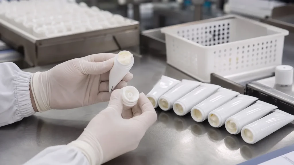
Bottom-up filling starts the nozzle near the tube bottom and raises it as product enters. The objective is to keep the outlet appropriately positioned relative to the rising product without scraping the tube or trapping air. A profile copied from another tube diameter may be wrong even for the same cream.
Divide the motion into controllable stages: approach, fill start, synchronized rise, deceleration, cutoff, suck-back and withdrawal. Tune the slowest representative speed first so the mechanism is visible, then increase output while preserving the product behavior.
If the nozzle rises too quickly, product can fall and fold over air. If it rises too slowly, the nozzle may drag through the cream, smear the wall or displace product upward. Use a transparent development tube where appropriate, section filled samples, or employ another approved inspection method to reveal hidden voids.
Coordinate the final cutoff with nozzle height. The clean-tail margin must account for product rebound, tube handling and the closure zone. Do not set fill level from appearance alone; relate it to net contents, density and the approved seal or fold geometry.
Verify tube centering and transport stability
The nozzle must enter the tube without touching the wall. Check holder or puck fit, tube ovality, closure seating, lift alignment and nozzle runout. A centering error can produce one-sided smearing and may be mistaken for a product-flow issue.
Inspect tubes from every approved supplier and cavity. Plastic and laminate tubes can vary in stiffness and ovality; aluminum tubes can be dented during handling. Define incoming checks that matter to filling: internal diameter, straightness, artwork mark, length and fit in the holder.
Observe indexing acceleration and tube presentation. If the machine squeezes or tilts a filled tube, product can move into the tail before sealing. Stabilize the holder, transport and timing rather than lowering the fill unnecessarily.
The cream tube filling machine overview explains the equipment sequence. For defect control, use station-specific checks and keep the investigation upstream of sealing until the clean tail is proven.
Prevent product from reaching the seal zone
Tail contamination begins at filling. Establish a minimum clean-tail margin for each tube and closure process. Confirm it immediately after filling, before hot air, ultrasonic energy or metal folding can hide the original condition.
Control fill mass, density and fill height together. A weight that is correct for an aerated batch can occupy more volume than a deaerated batch. This is why density and air content belong in the investigation. Avoid compensating for variable volume by lowering the nominal weight without quality approval.
Check stringing, splashing and transport forces. A thin strand can attach to the nozzle and land on the tail as the tube indexes. Excessive acceleration can push product upward. Tube squeezing can move product into the closure zone even when the initial height was acceptable.
The tube filling and sealing guide covers downstream closure. Do not adjust sealing temperature or jaw pressure to solve product that should never have entered the seal zone.
Use a controlled trial protocol
Define the response variables before testing: individual weight, visible string length, drip count, air-pocket result, clean-tail margin, wall smear and reject count. Hold unrelated settings constant and change one mechanism at a time unless a designed experiment is justified.
Start with the approved product condition and representative tubes. Record batch number, time after manufacture, temperature, density, viscosity method, hopper level, pump and nozzle parts, recipe parameters and ambient conditions where relevant. Photograph defects using the same angle and scale.
Challenge the operating window. Test minimum and maximum product temperature, hopper level, dose and planned speed. Include a stop and restart, because product can settle, cool or relax during downtime. Confirm the first tubes after restart rather than mixing them into the full sample.
| Trial phase | Purpose | Minimum record |
|---|---|---|
| Baseline | Reproduce the defect | Product condition, settings and sequential samples |
| Mechanism check | Separate air, pressure, nozzle and motion causes | One controlled change and observed response |
| Parameter window | Define robust limits | Low, nominal and high settings with quality results |
| Sustained run | Confirm stability | Good output, rejects, stops, weights and temperatures |
| Restart test | Test downtime recovery | Hold duration, first-piece results and purge requirement |
Troubleshooting checklist and King Pack review
- Confirm product temperature, density and viscosity method
- Verify upstream deaeration and absence of hopper vortex
- Check hopper level, inlet flooding and feed-pressure stability
- Inspect pump valves, seals, hoses and refill timing
- Verify nozzle bore, shutoff condition and suck-back
- Center the tube and measure nozzle runout
- Tune bottom-up motion with the actual tube diameter
- Measure clean-tail margin immediately after filling
- Link individual weights to refill events and stops
- Retain approved samples, settings and defect photographs
King Pack can review product rheology, tube drawings, dose range, target speed and defect photographs to prepare a filling-process trial. The useful outcome is a documented combination of hopper condition, dosing setup, nozzle, motion profile and acceptance evidence—not an unsupported promise that one setting solves every formula.
Frequently asked questions
Why does cream string from the filling nozzle?
Common causes include low product temperature, a narrow nozzle, slow shutoff, insufficient suck-back or a damaged tip. Adjustments should be verified together with the start of the next dose.
What causes air pockets in filled tubes?
Air may already be entrained in the batch, enter through a vortex or starved pump inlet, or be trapped by a poor nozzle start position and lift profile.
Can increasing suck-back eliminate all dripping?
No. Excessive suck-back can pull air into the nozzle and disturb the next fill. Correct product condition, nozzle bore and shutoff first, then use the minimum effective suck-back.
Why does fill weight vary when calibration is unchanged?
Changing temperature, density, air content, hopper level, inlet pressure, valve leakage or incomplete pump refill can alter individual doses even when the nominal calibration is unchanged.
How can product in the tube seal zone be prevented?
Maintain a validated clean-tail margin, stop stringing and splashing, stabilize tube transport, control air content and verify product height before the closure station.
Should a hopper agitator run continuously?
Only if the formulation requires it. Use the lowest proven agitation that maintains uniformity without introducing a vortex or air.
What data should be sent for a filling-process review?
Send viscosity and temperature data, density, tube drawing and samples, fill range, speed target, current nozzle and pump details, recipe settings, sequential weights and defect photographs.