
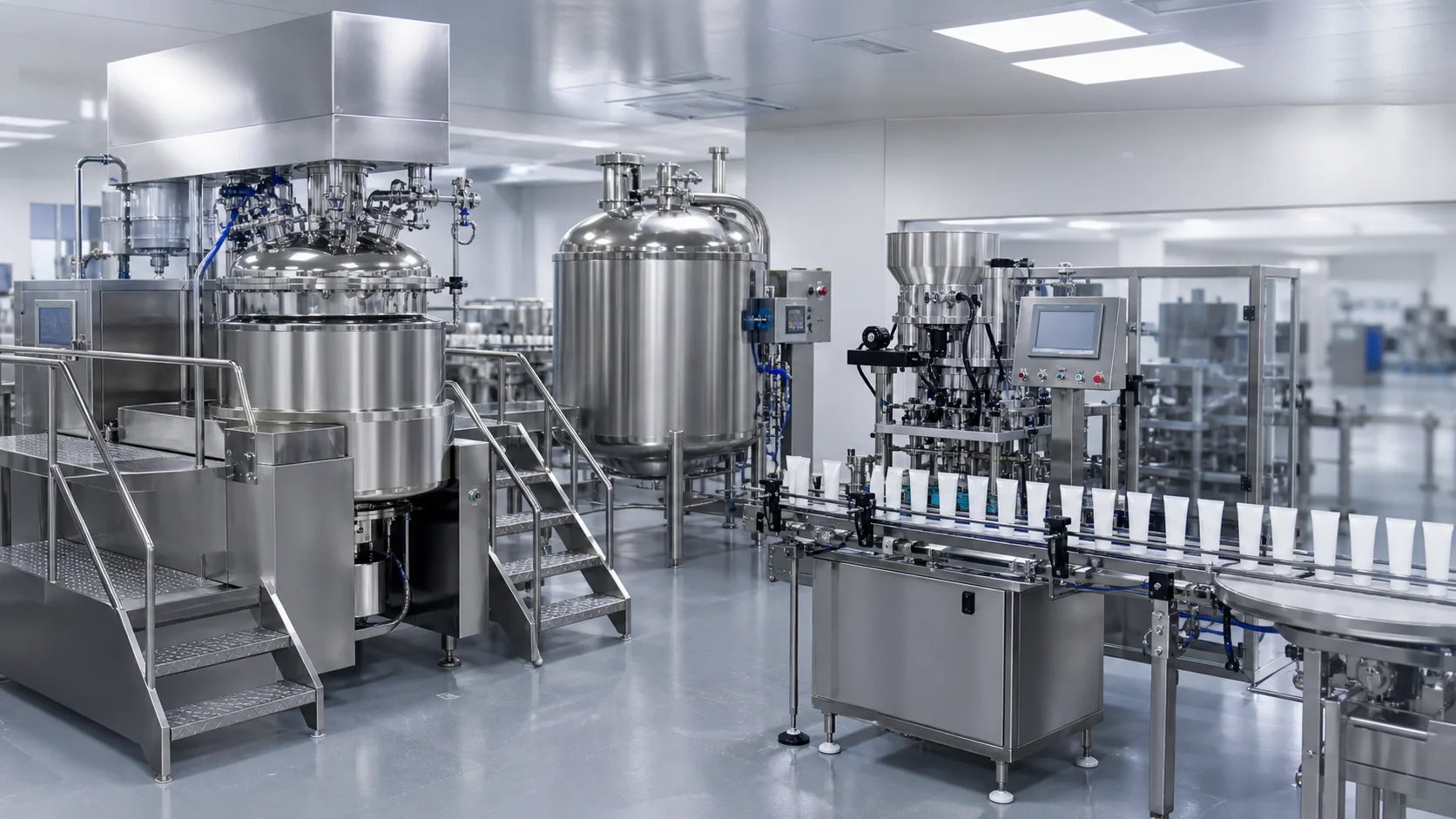
A cosmetic cream production line must be designed as one material-and-package flow, not as a mixer, filler and cartoner purchased independently. The critical decisions sit at the interfaces: when the emulsion is released, how it is cooled and deaerated, whether a buffer tank is needed, how the cream reaches the filler, and whether the packaging section can consume each batch without long waits or repeated heating.
Quick answer: begin with batch size, formula behavior, package formats and required saleable output. Map the water and oil phases into a vacuum emulsifying stage, define the quality hold and transfer conditions, then balance the buffer, filling and packing rates. A line is well designed when product quality remains inside its approved window while the packaging equipment receives stable pressure, temperature and supply.
End-to-end cream line map
| Stage | Main equipment | Interface that must be defined | Acceptance evidence |
|---|---|---|---|
| Water and oil preparation | Phase vessels, load cells, powder/liquid addition | Addition order, temperature, transfer endpoint | Recipe record and phase-temperature trend |
| Emulsifying | Vacuum mixer, anchor, homogenizer, jacket | Phase transfer rate, shear exposure, vacuum profile | Appearance, viscosity, density and temperature uniformity |
| Cooling and quality hold | Main vessel or finishing vessel | Release criteria and maximum hold time | Approved sample and recorded hold conditions |
| Transfer and buffering | Sanitary pump, pipework, optional buffer tank | Product temperature, pressure, air exclusion and residual volume | Transfer yield and pressure/temperature trend |
| Filling | Jar/bottle filler or tube filler | Hopper feed, dosing range, nozzle profile and refill logic | Fill-weight study and defect record |
| Sealing and packing | Tube sealer, coder, cartoner, case packer | Line speed, reject handling and accumulation | Sustained line trial with good-count reconciliation |
Define the production target before selecting equipment
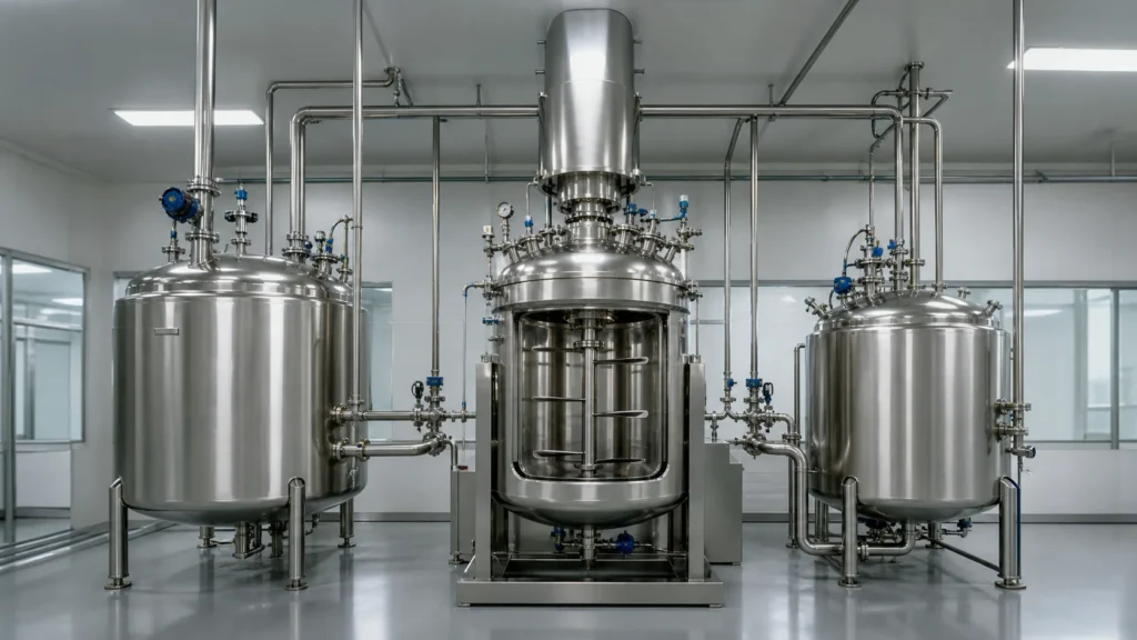
Specify saleable units per shift, not only a machine nameplate speed. Start with pack size, planned SKU mix, campaign length, shifts, cleaning time, format-change time, expected rejects and production availability. A 60-tube-per-minute filler does not deliver 28,800 saleable tubes in an eight-hour shift if the batch is late, the hopper repeatedly runs empty or packaging changeovers occupy two hours.
Translate demand into batch and packaging quantities. For example, a 600 kg batch divided into 100 g packs represents 6,000 theoretical units before samples, pipe hold-up and rejects. At 50 units per minute, the net filling window is about two hours. This arithmetic reveals whether one mixer can feed one packaging line, whether a buffer is useful, and how many batches are required per campaign.
Create a SKU matrix with formula family, viscosity range, density, batch size, package type, fill mass, tube or container dimensions, closure, code, carton and required output. Mark the worst case separately for mixing, cooling, transfer, dosing and sealing. The thickest product may challenge the pump, while the smallest dose may be the most demanding filling accuracy case.
Prepare water and oil phases with a controlled recipe
Many creams use separately prepared water and oil phases before emulsification. The water phase may contain water-soluble ingredients, humectants, emulsifiers and thickeners; the oil phase may require melting waxes or fatty components. The actual sequence is formula-specific, so the line must support controlled charging, heating, agitation and transfer rather than assume one universal recipe.
Phase vessels should be sized for working volume, headspace and additions. Define load-cell or flowmeter accuracy, powder charging method, heating duty and transfer route. If powders hydrate rapidly, uncontrolled surface addition can create agglomerates. Official high-shear mixing guidance from Silverson notes that powder wet-out and hydration can be difficult with conventional agitation and that the process benefits from controlled high-shear dispersion.
Record critical recipe parameters: ingredient confirmation, charge mass, mixing speed, phase temperature, hold time and transfer authorization. Heat-sensitive actives, fragrance and preservatives may be added later at lower temperature. Provide dedicated ports and a sequence that avoids exposing these materials to an unnecessary vacuum or shear stage.
Use the King Pack cosmetic industry equipment overview to map the main process and packaging machine families. The line specification still needs formula-specific working ranges and acceptance tests.
Configure the vacuum emulsifying stage around quality endpoints
The vacuum emulsifying mixer combines bulk circulation, localized high shear, heat transfer and deaeration. The anchor and wall scrapers move viscous material across the vessel and jacket; the rotor-stator homogenizer disperses and emulsifies material in its shear zone. These functions must work together throughout heating, emulsifying and cooling.
Define what “finished” means. Suitable endpoints may include appearance, absence of visible agglomerates, viscosity measured by an agreed method, density, pH, temperature uniformity and a formulation-owned droplet-size requirement. Do not use mixer time alone as the quality criterion. A recipe should reach measurable results inside a permitted parameter window.
Vacuum duty also needs a purpose. It may assist closed transfer, reduce aeration during mixing or remove entrained air after emulsification. A staged vacuum profile is often safer than an immediate maximum vacuum because some formulations foam or contain volatile ingredients. Specify separator protection, controlled venting and a product-specific deaeration endpoint.
Heating and cooling capacity should be based on batch mass, start and target temperatures, utility conditions and required time. Cooling is frequently the schedule constraint for a viscous cream. Ask the supplier to state utility temperatures, flows and agitation settings behind any time estimate, then verify the curve during the factory trial.
For a deeper equipment explanation, see the vacuum emulsifying mixer application guide. This line-planning page focuses on what happens before and after the mixer.
Establish a release point after cooling and deaeration
Packaging should not begin merely because the mixing timer has ended. Create a quality hold between processing and filling. Define who releases the batch, which tests are performed, how samples are taken, and the maximum time the product can remain in the vessel or buffer under stated temperature and agitation conditions.
The fill temperature affects viscosity, stringing, dose pressure and seal-area cleanliness. A cream that fills smoothly at 35 C may become difficult to pump at 25 C; another formula may be too fluid at the higher temperature. Establish a validated filling window and design the transfer and hopper system to maintain it without degrading the product.
Avoid unnecessary recirculation after the endpoint. Continued shear can change structure, add heat or introduce air through a poor return path. If slow agitation is required during the hold, define the minimum speed that maintains uniformity without overprocessing.
Document deviations. If the batch is held longer than planned, determine whether it needs resampling, controlled remixing or rejection according to the site quality procedure. The machine controls can record time and temperature, but the manufacturer owns the disposition rule.
Design transfer and buffer storage as a quality-controlled step
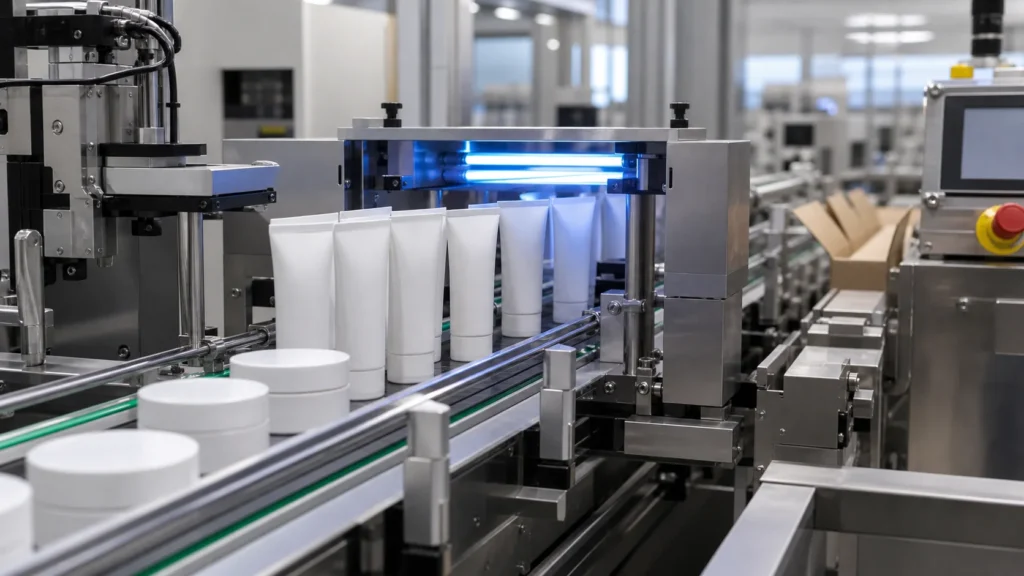
Transfer piping is part of the process. State distance, elevation, pipe diameter, bends, valves, pump type, receiving pressure and cleanability. For high-viscosity creams, a positive-displacement pump or pressure-assisted transfer may be appropriate. Pump selection must account for shear sensitivity, inlet conditions and the final viscosity, not only the warm bulk stage.
Minimize air entry and hold-up. Use a flooded suction where required, avoid poorly vented high points and define how the line is primed. Measure charged mass, samples, transferred mass and residue in the vessel, pump and pipe during trials. Recurring loss of a high-value cream can outweigh a small capital saving.
A buffer tank can decouple batch mixing from intermittent packaging stops, but it is not automatically beneficial. It adds residence time, product-contact surface, cleaning scope and residual volume. Use one when it solves a quantified scheduling or pressure-stability problem.
| Buffer question | If the answer is yes | Engineering response |
|---|---|---|
| Does packaging stop often while the mixer must start the next batch? | Processing and packing are tightly coupled | Size a buffer for a defined interruption, not a full batch by habit |
| Must the filler receive stable pressure? | Pump pulsation or vessel level affects dosing | Add controlled feed pressure and low-level interlocks |
| Does viscosity change during the hold? | Temperature or shear history affects fill behavior | Jacket and gently agitate the buffer; set a residence-time limit |
| Are product losses expensive? | Extra tank and pipe increase hold-up | Compare recovered yield with the scheduling benefit |
| Is changeover frequent? | Cleaning time may dominate | Favor a short, drainable route or mobile vessels where appropriate |
Select the filling route by package and product behavior
Creams may be filled into jars, bottles, airless containers or tubes. The package determines orientation, nozzle access, closure handling and downstream equipment. The formula determines hopper design, pump technology, nozzle diameter, shutoff, suck-back and filling profile.
For jars and bottles, evaluate piston, servo piston or another positive-displacement system based on viscosity, dose range, inclusions and cleaning needs. Use bottom-up or diving-nozzle filling when it reduces air pockets or splashing. Test the smallest and largest dose and verify that refill pressure does not disturb dosing.
For tubes, product enters through the open tail before sealing. The filler must orient the artwork, dose without contaminating the seal zone, seal or fold the tail, code it and trim if applicable. Plastic and laminate tubes generally use a welding process such as hot air or ultrasonic; aluminum tubes use folding and crimping. These are different station requirements, not simply recipe selections.
The tube filling and sealing machine guide explains the sealing stage in more detail. During line design, require a representative sample trial using the actual cream, tube, artwork orientation and code.
Balance tube filling, sealing, coding and cartoning
The tube filler should be rated on sustained good output with the selected diameter, dose and sealing system. Downstream equipment must accept that flow. A cartoner slower than the tube filler creates accumulation; no accumulation causes frequent upstream stops. Define the control interface, starvation and blockage signals, reject tracking and restart behavior.
Coding location affects inspection and reject logic. Confirm code content, print technology, contrast, position and verification. Rejects should be removed at a controlled point and reconciled against production counts. When a defective seal or missing code is detected, the system should preserve traceability rather than merely reduce a counter.
Allow safe accumulation where it prevents minor downstream events from stopping the filler, but do not use long conveyors to hide a fundamental speed mismatch. Evaluate the average cycle, microstops, changeover and material replenishment for tube supply, leaflets, cartons and cases.
For multiple pack formats, create a changeover map. Separate recipe parameters from mechanical change parts and packaging components. Record the owner, target time and verification step for each change. A line that runs quickly but requires an unplanned half shift to change formats may miss the production target.
Integrate cleaning, utilities and controls
List all product-contact components from phase vessels through the filling nozzle. Decide which are cleaned in place, washed out of place or cleaned manually. Review spray coverage, drainability, seal access, dead legs and chemical compatibility. A buffer tank added for scheduling can double the cleaning burden if the cleaning strategy is not designed at the same time.
Build a utility schedule with simultaneous peaks: steam or hot water, chilled water, compressed air, vacuum, electricity and cleaning water. Average consumption alone can hide a peak that limits heating, cooling or pneumatic equipment. Specify supply pressure, temperature, flow, quality and return conditions at the machine boundary.
Define line controls at functional interfaces. The filler should not run dry; the transfer pump should respond to hopper level without creating excessive pressure; the packaging line should signal blockage before tubes accumulate unsafely. Decide which machine is the line master, which data are recorded, and how batch and packaging identifiers are linked.
Use a line-balance calculation before approving the layout
Calculate the duration of each processing and packing step for every major SKU. Include preparation, heating, emulsification, cooling, testing, transfer, filling, changeover and cleaning. Draw a time line showing when the mixer, buffer, filler and cartoner are occupied. This exposes waiting and confirms whether a buffer or second vessel creates real capacity.
Review the physical layout with material, people and waste flows. Separate raw-material staging, clean components, finished goods and rejected packaging. Provide maintenance access, change-part storage, safe lifting, sampling space and utility corridors. A compact layout is valuable only if operators can clean and service it.
During FAT, run an integrated scenario rather than isolated dry cycles. Use representative product or an agreed simulant and production packaging. Demonstrate startup, steady output, a brief downstream stop, restart, low-level response, reject handling and changeover checks. Record assumptions where the test material differs from the commercial formula.
Project-input checklist for a cosmetic cream line
- Formula family, density and viscosity versus temperature
- Minimum, normal and maximum batch size
- Heating, emulsifying, cooling and release criteria
- Maximum permitted hold time and filling-temperature window
- Transfer distance, elevation and required delivery pressure
- Package types, drawings, materials, dimensions and closure systems
- Fill range, target output, SKU mix and campaign length
- Coding, inspection, cartoning and case-packing requirements
- Cleaning method, changeover target and utility conditions
- Required batch records, line reports, roles and data interfaces
- FAT products, formats, sampling plan and acceptance criteria
How King Pack can support the line concept
King Pack can configure the process and packaging scope around the customer’s formula, batch, package and output inputs. A project may combine phase preparation, vacuum emulsification, transfer or buffering, liquid or high-viscosity filling, tube filling and sealing, coding and end-of-line equipment. The correct scope depends on actual material behavior and site utilities.
For an integrated-line review, provide batch size, formula properties, package drawings, filling range, target output, available floor plan and utility data. The useful deliverable is not a generic machine list; it is a process flow, equipment boundary, interface schedule and FAT plan that the project team can verify.
Frequently asked questions
What equipment is needed for a cosmetic cream production line?
A typical line can include water and oil phase vessels, a vacuum emulsifying mixer, transfer equipment, optional buffer storage, a jar/bottle or tube filling machine, sealing or capping, coding, inspection, cartoning and case packing. The exact scope depends on the formula and package.
Does every cream line need a buffer tank?
No. A buffer is justified when it improves line balance, maintains filler feed or lets processing continue through packaging interruptions. It also adds hold time, cleaning and product loss, so its benefit should be calculated.
How should mixer batch size be matched to filler speed?
Convert batch yield into saleable units, then divide by the sustained good filling rate. Include samples, residual product, rejects, changeovers and cleaning. Use the resulting time line to determine whether the mixer, buffer or filler is the constraint.
Why is filling temperature important for cream?
Temperature changes viscosity and can affect pumping, dose pressure, stringing and air pockets. Define a product-specific filling window and keep the vessel, transfer route and hopper inside it.
Can one line fill both jars and tubes?
The same upstream processing system may feed separate packaging machines, but jars and tubes require different handling and closing systems. Changeover between packaging routes must include transfer, cleaning, scheduling and product-hold controls.
What should be tested during FAT?
Test representative batch and package extremes, transfer stability, sustained output, fill quality, sealing or closing, coding, rejects, stop/restart behavior and changeover checks. Record the product or simulant, settings and acceptance criteria.
How do I request an integrated line proposal?
Send the formula properties, batch range, package drawings, fill sizes, output target, campaign plan, floor space, utilities and required documentation. These inputs allow the equipment and interfaces to be sized together.