
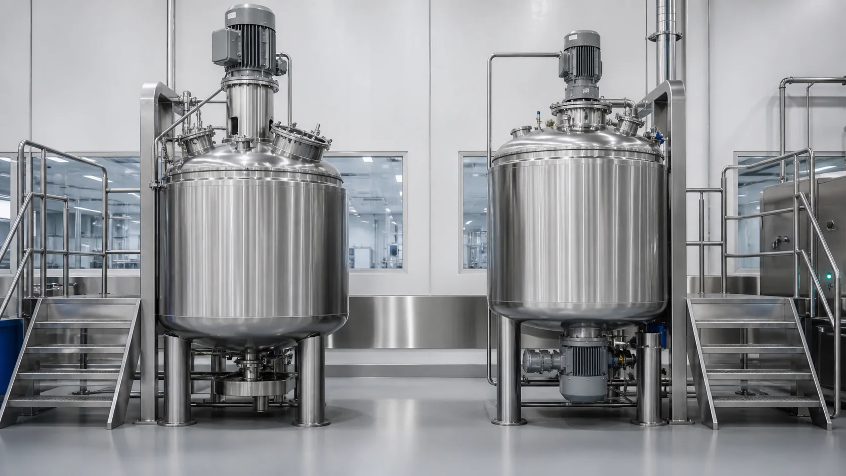
The position of a rotor-stator homogenizer changes how product reaches the shear zone, how low the batch can run, where seals are maintained and how the vessel is cleaned. It does not, by itself, determine emulsion quality. A top-entry homogenizer can outperform a bottom-entry unit when its head position and bulk flow suit the vessel; a bottom-entry homogenizer can be the better choice when low-level processing and short product circulation are critical.
Quick answer: choose from the complete process. Favor a top-entry concept when the project needs flexible head placement, top-side maintenance access or a configuration that avoids bottom-drive constraints. Favor a bottom-entry concept when the shear zone must remain effective at a low liquid level, when a compact product path supports viscous circulation, or when an immersed shaft would complicate cleaning. For thick creams and ointments, either layout normally needs a correctly sized anchor or scraper to feed the homogenizer.
Quick comparison table
| Decision factor | Top-entry homogenizer | Bottom-entry homogenizer | What to prove |
|---|---|---|---|
| Shear-zone location | Suspended from the vessel cover at a defined depth | Located close to the vessel bottom or lower sidewall | Complete circulation at minimum and maximum batch |
| Minimum batch | Limited by head submergence and circulation pattern | Often supports lower liquid levels | Stable operation without air draw or dry running |
| High-viscosity turnover | Depends on anchor feed across vessel depth | Short intake path can help, but still needs bulk feed | No stagnant top, wall or bottom zones |
| Powder wet-out | Depends on feed point and flow into the head | Subsurface draw-in can be integrated near the lower shear zone | Addition-rate test with no visible agglomerates |
| Seal and maintenance | Drive and upper seal are accessible from the top platform | Product-side seal is near the floor and needs service clearance | Safe removal route and realistic maintenance time |
| Cleaning | Longer immersed assembly may add surfaces | No long immersed shaft, but bottom seal and cavity need coverage | Drainability, spray coverage and post-clean inspection |
| Vessel and building | Requires headroom and cover support | Requires foundation/floor and underside access | General arrangement with open-door and removal envelopes |
How each layout circulates product
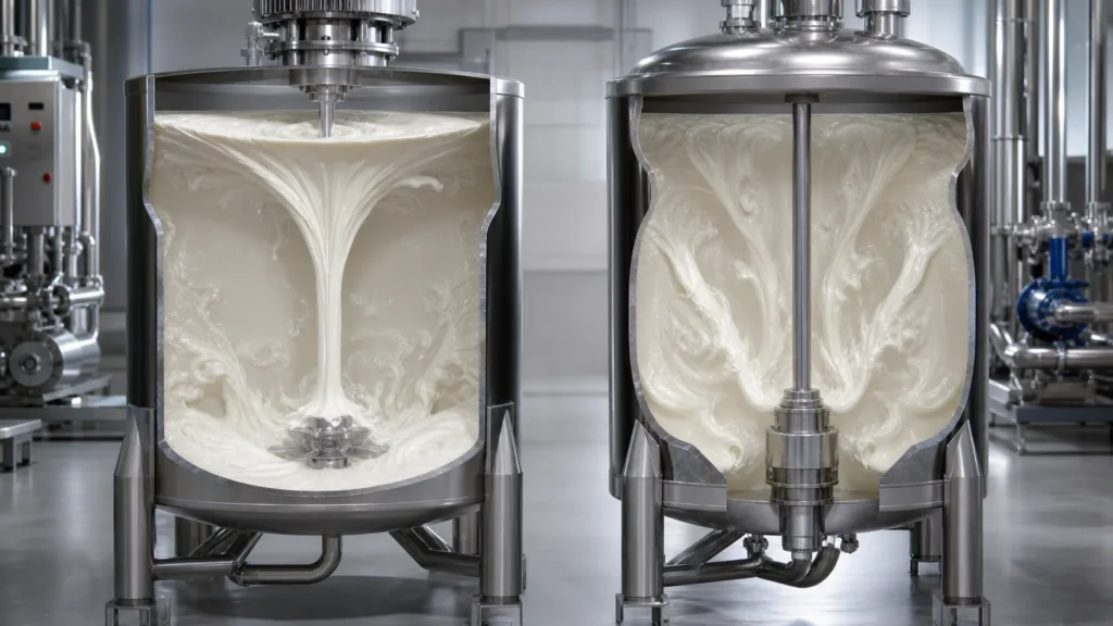
A rotor-stator homogenizer draws material into the center of its workhead, exposes it to high local shear and expels it radially through the stator. Official high-shear mixer references describe this intake, milling and radial discharge cycle. The important project question is how quickly untreated bulk product returns to the head.
In a top-entry layout, the homogenizer head is suspended in the product. Its elevation can be selected relative to liquid depth, vessel diameter, anchor and baffles. Radial discharge may create a useful circulation loop, but the pattern changes as the batch thickens. A visible surface vortex can coexist with a slow-moving bottom or wall zone.
In a bottom-entry layout, the workhead sits near the lowest vessel zone. Discharge begins close to the curved bottom and can be redistributed upward by the anchor or scraper. Silverson’s official bottom-entry description explicitly pairs high-shear treatment with a slow stirrer or scraper for viscous products. IKA also notes that bottom installation can support dispersion at relatively low vessel levels. These are useful design principles, not guarantees for every formulation.
Map the expected flow as a system. Mark the homogenizer intake and discharge, anchor pumping direction, scraper movement, baffles, addition ports and outlet. If a recirculation loop is used, include its takeoff and return points. The diagram should explain how material from the top, wall and bottom reaches the shear zone repeatedly.
The broad vacuum emulsifying mixer types overview explains general equipment families. The comparison here stays focused on homogenizer position and its process consequences.
Batch minimum and vessel geometry
Minimum batch is not simply a percentage of nominal vessel volume. The homogenizer must remain covered, avoid drawing air and receive enough product for stable recirculation. The anchor and temperature probe must also remain functional, and the jacket should not create a hot wall above the product level during heating.
A top-entry head has a fixed or adjustable operating depth. Ask for the lowest permitted level above the intake and stator, then check that level against the minimum batch density and vessel geometry. A conical or dished bottom can leave a useful pool below the main cylindrical section, while a flat bottom may require a different head elevation and anchor clearance.
A bottom-entry head is naturally close to the lowest product level, which can extend the working range. Low-level capability still requires evidence. Air can enter through a vortex or exposed return stream; a thick product may bridge above the intake; and a large bottom nozzle can compete for the same space. Confirm the minimum batch with the exact vessel, head, anchor and recipe sequence.
At maximum batch, check the opposite problem: the homogenizer may treat the lower zone quickly while turnover from the upper product column becomes slow. The anchor should move material vertically as well as circumferentially. Temperature probes at different heights and timed samples can reveal whether the full batch responds uniformly.
Request a working-volume drawing rather than a marketing range. It should show minimum, normal and maximum product levels, homogenizer position, impeller sweep, probe locations, jacket zones, ports and outlet. Add the foam and vacuum expansion allowance above the maximum working level.
Powder induction and wet-out
Powder performance depends more on the feed method and local liquid velocity than on whether the motor is above or below the vessel. Surface dumping can allow gums, polymers or pigments to float, dust or form agglomerates. Controlled subsurface addition exposes powder to moving liquid before it hydrates into a protective shell.
A top-entry homogenizer may accept powder through a port positioned near its circulation loop, or the project may use a separate premix pot or inline induction device. The head must remain fully flooded while powder is added. If the powder enters above a thick surface layer, the homogenizer can be powerful yet starved of the ingredient.
A bottom-entry homogenizer can be integrated with suction that draws liquids or solids toward the shear zone. Official vacuum processing systems use this principle for immediate wetting and dispersion. The draw-in rate must be controlled. Feeding faster than the liquid can wet and carry the powder causes blockage, incomplete dispersion or a sudden vacuum surge.
Build a powder table for the trial: ingredient, bulk density, addition amount, addition temperature, desired rate, hydration behavior and acceptance method. Challenge the hardest powder at the highest viscosity expected during addition. Screen the batch or use the site’s validated test to look for undispersed material. A short addition time is not success if later mixing or rework is required.
High-viscosity circulation
Cream and ointment processing often begins at lower viscosity and becomes much thicker during cooling or after polymer hydration. Rotor-stator shear is concentrated in a small zone. The slow-speed anchor or scraper must deliver thick bulk product to that zone and renew the wall film for heat transfer.
With a top-entry homogenizer, the long shaft and head position must be compatible with the anchor sweep. Confirm mechanical clearances at all speeds and temperatures. At high viscosity, the anchor may need to push product downward or across the head rather than merely rotate it around the wall. Torque at final viscosity and restart torque after a planned hold are important acceptance inputs.
With a bottom-entry homogenizer, the short path near the vessel base can support intake, but the upper batch still has to move downward. A well-designed anchor can feed the lower head and bring homogenized product back through the vessel. Without that bulk flow, the lower region may be overprocessed while the top remains nonuniform.
Do not select only from maximum viscosity. Provide the full viscosity-temperature curve and note whether the material is shear-thinning, thixotropic or yield-stress dominated. The supplier should explain the test method and the condition used for motor and seal sizing. A viscosity number measured after the batch at room temperature may not represent the load during processing.
Useful trial evidence includes temperature difference between probes, time for a tracer to become uniform, samples from more than one height, motor load and the time to reach the defined quality endpoint. A transparent pilot vessel can reveal flow mechanisms, but production-scale confirmation is still required because depth and diameter change the circulation path.
Vacuum and deaeration interaction
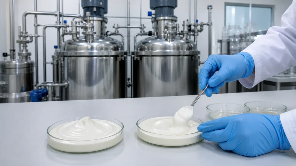
Both top- and bottom-entry homogenizers can operate in a vacuum vessel if their shafts, seals, flanges and controls are designed for the pressure and temperature range. Vacuum is used for ingredient draw-in, reduced aeration or final deaeration. Its benefit depends on recipe control, not installation position alone.
The top-entry assembly passes through the vessel cover. Review the seal arrangement, shaft stability and cover loads under vacuum. Confirm how the unit is lifted or removed without damaging the seal or interfering with ports and the anchor drive.
The bottom-entry seal sits at a product-wetted lower boundary. Review allowable pressure direction, seal-flush or barrier requirements, leak detection and the safe response to a seal alarm. The design must protect both the batch and the work area below the vessel.
During deaeration, high shear can break large bubbles into smaller ones faster than vacuum removes them. The recipe may need reduced homogenizer speed or a separate low-shear vacuum hold. Use final density, appearance or another product-specific endpoint. Do not compare concepts only by the deepest vacuum shown on a data sheet.
Seal access and maintenance
Maintenance access often decides between two technically workable layouts. A top-entry drive is above the vessel, usually on the cover or a support frame. Technicians need safe platform access, overhead clearance and a method to remove the shaft and head. If the lid lifts hydraulically, show the complete raised envelope and maintenance lockout.
A bottom-entry drive requires space below or beside the vessel. The foundation, frame and floor opening must allow seal and motor service without moving unrelated equipment. Product leakage from a damaged seal must be contained and detected. A compact processing room can become difficult to maintain if the service envelope is ignored.
Ask for a component-level maintenance sequence. How are the rotor, stator, shaft, bearings and mechanical seal removed? Which tools and lifting points are required? Which parts are routine spares? What inspections follow a dry-running event or product ingress? Compare the time from safe isolation to return-to-service, not only the price of a seal kit.
Mechanical design should also consider vibration and shaft deflection. Long top-entry shafts require appropriate support and operating-speed review. Bottom-entry assemblies reduce immersed shaft length but transfer loads through the vessel base. The supplier should own the integrated vessel and mixer calculation or clearly define interface responsibilities.
Cleaning and changeover
Top entry can expose more immersed shaft and support surfaces to product. These surfaces need spray coverage, drainability and access for inspection. A lifted head can improve manual inspection but introduces an opening operation and safe handling requirement.
Bottom entry avoids a long immersed shaft and can leave fewer internal obstructions. However, the lower workhead, seal, outlet transitions and any recirculation cavity must be cleaned and drained. Low-point location helps drainage only if there are no trapped pockets behind the stator or seal housing.
For either layout, draw the cleaning path. Identify spray devices, cleaning-solution inlet, flow through the homogenizer, return, drain and sampled locations. Define whether the homogenizer runs during cleaning, at what speed, and how seal surfaces are exposed. Include the vacuum separator, powder ports and discharge line in the same boundary.
Changeover risk is formula-specific. Pigmented creams, potent ointments, fragrances and wax-rich products may challenge different areas. Use the site’s product matrix to select a worst case, then agree residue limits and inspection methods. Equipment cleanability should be demonstrated; it cannot be inferred from a polished surface alone.
Scale-up and production trial plan
Scale-up should preserve the mechanisms that matter: rotor-stator shear, product turnover, batch depth, anchor pumping, thermal exchange and ingredient addition. Copying laboratory rpm to a larger rotor is unsafe and technically meaningless. Compare tip-speed range, workhead geometry, power, flow and exposure time while respecting product sensitivity.
Top-entry scale-up may change shaft length and head elevation relative to the vessel. Bottom-entry scale-up may keep the shear zone near the base while increasing the distance from the upper product layer. In both cases, vessel proportions can change circulation. The selected production unit should be tested with the planned anchor and thermal cycle, not a homogenizer in isolation.
A practical trial plan includes:
- Minimum and maximum working batch.
- Lowest-viscosity charging stage and highest-viscosity cooling stage.
- Hardest powder at the intended addition rate.
- Heating and cooling curve with stated utilities.
- Vacuum draw-in and deaeration endpoint.
- Samples from top, middle and bottom at defined times.
- Stop and restart at a justified worst-case condition.
- Discharge yield, residual product and cleaning inspection.
Record the exact test configuration: vessel, head, stator, anchor, scraper, speeds, batch mass, product or simulant, temperatures, vacuum profile and sample method. A trial is only transferable to the purchase specification when its conditions are documented.
For pharmaceutical ointment and cream projects, the pharmaceutical vacuum emulsifying mixer application provides the broader industry context. Product-specific quality, cleaning and validation requirements still belong in the user requirement specification.
Selection checklist
| Question | Why it changes the choice | Required evidence |
|---|---|---|
| What is the true minimum batch? | Determines head coverage and stable circulation | Witnessed low-level test |
| Where does viscosity peak? | Sets anchor torque, homogenizer feed and restart duty | Viscosity-temperature data and motor-load record |
| How are difficult powders added? | Controls wet-out, dust and agglomeration | Addition-rate trial and dispersion test |
| Is top or underside service space available? | Determines maintainability and layout | General arrangement with removal envelope |
| What is the cleaning boundary? | Exposes hidden seals, cavities and recirculation hold-up | Cleaning flow diagram and inspection access |
| Which quality endpoint proves completion? | Prevents selection by mixing time alone | Sampling plan and acceptance results |
| How will the design scale? | Prevents lab performance from being assumed at production depth | Documented scale-up rationale and production trial |
Select the position only after reviewing this evidence. A bottom homogenizer should not be chosen because it sounds better for “high viscosity,” and a top-mounted homogenizer should not be chosen only because it is familiar. The decision must fit the batch range, product path, building, cleaning method and maintenance plan.
King Pack can compare the two arrangements against a specific vessel and formula. Share vessel size, minimum batch, viscosity versus temperature, powder-addition method, required vacuum stages, cleaning method and available service space through the cosmetic processing and filling page. The output should be a position-specific flow concept and trial protocol, not a generic equipment recommendation.
Frequently asked questions
Is a bottom-entry homogenizer better for small batches?
It often supports lower liquid levels because the head is near the vessel bottom, but the exact minimum depends on geometry, air draw, anchor feed and probe coverage. Require a low-level trial.
Does a top-entry homogenizer create more air?
Not necessarily. Aeration depends on head submergence, surface vortex, speed, addition method and vacuum recipe. Either layout can run with low aeration when configured correctly.
Which layout is better for very thick ointment?
Neither position is sufficient by itself. The decisive factor is whether the anchor or scraper moves the entire batch through the shear zone at final viscosity and during restart.
Which design is easier to clean?
Bottom entry removes a long immersed shaft, while top entry can offer direct access when the cover is lifted. Compare actual product-contact surfaces, seal cavities, spray coverage, drainability and inspection access.
Can powder be inducted directly into either homogenizer?
Yes, depending on the system design. The feed path, vacuum source, liquid flow and powder rate must be matched and tested to prevent blockage or incomplete wet-out.
Does homogenizer position affect heating and cooling?
Indirectly. Position changes bulk circulation and how well product renews at the jacket wall. The anchor, scraper and vessel geometry usually have a stronger direct effect on thermal uniformity.
What data should be sent with an RFQ?
Provide batch range, vessel dimensions, formula sequence, viscosity-temperature curve, powder properties, quality endpoints, vacuum and thermal profile, cleaning method, service-space limits and trial samples.