 Skip to content

Choosing between a filling-and-capping monoblock and separate machines is a line-design decision, not a contest between “compact” and “flexible.” A monoblock places filling and capping functions on one synchronized base, reducing transfers and floor space. A modular line uses independent fillers, cappers and conveyors, giving each process more buffering, service access and upgrade freedom.
The right answer depends on the package, number of formats, required output, reject strategy, available floor area and the cost of a stopped line. Compare both concepts with the same product, bottle, cap, operating schedule and acceptance criteria. A headline speed without those assumptions is not a meaningful comparison.
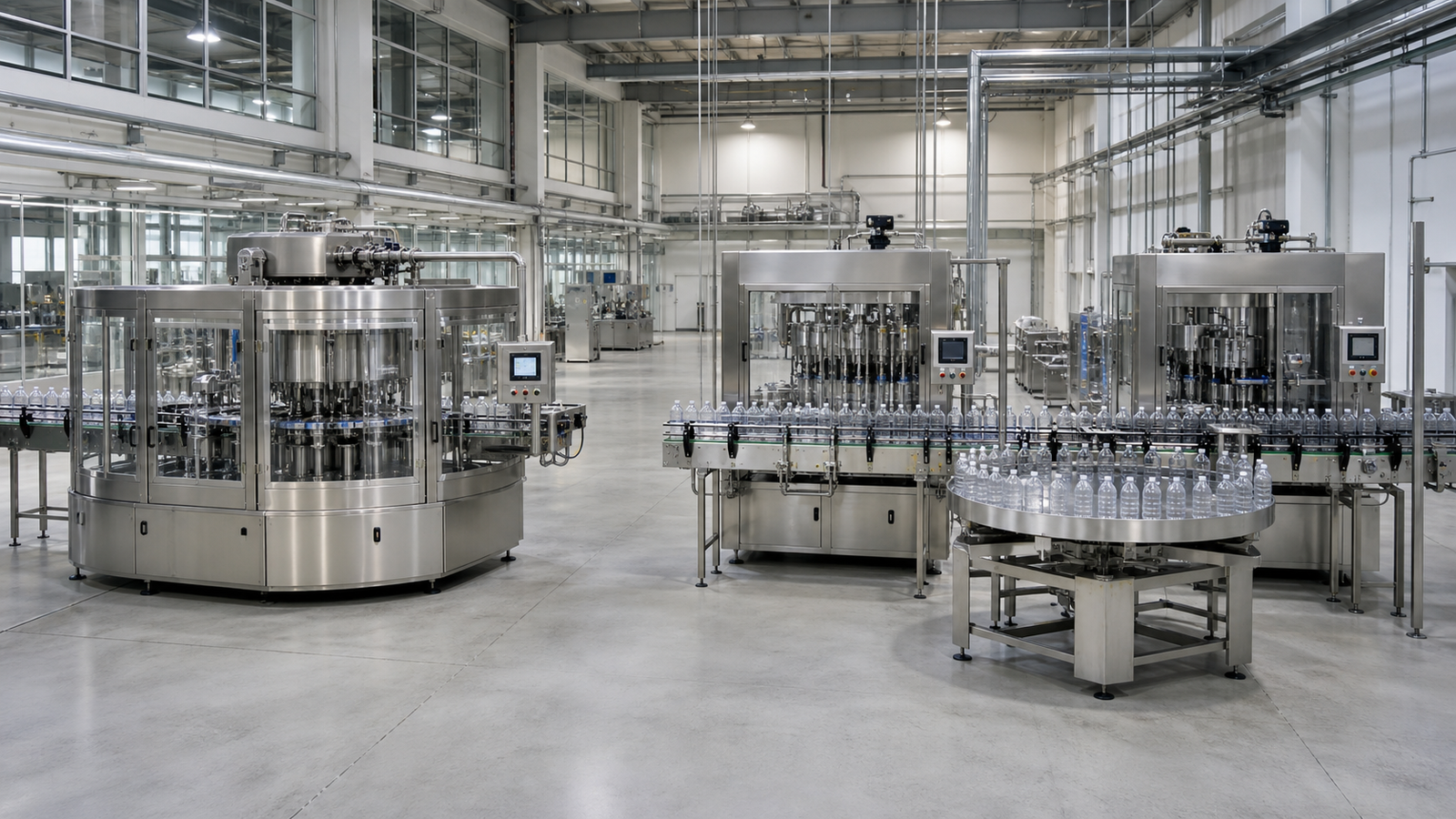
Quick answer: which line concept should you choose?
Choose a filling-capping monoblock when the package family is stable, footprint is limited, transfers must be tightly controlled and one supplier can qualify the combined process. Choose separate machines when frequent format changes, process-specific inspection, accumulation, independent upgrades or future line expansion are more important than minimum footprint.
Neither layout guarantees better overall equipment effectiveness. A monoblock can remove conveyor losses, but one fault can stop the complete block. A modular line can isolate faults with accumulation, but extra transfers, sensors and interfaces create more failure points. Evaluate availability, performance and quality at line level.
Monoblock vs separate machines at a glance
| Decision factor | Filling-capping monoblock | Separate filler and capper |
|---|---|---|
| Footprint | Usually smaller because functions share a frame and pitch | Usually larger because of conveyors, guards and accumulation |
| Product transfer | Short, synchronized and easy to enclose | More handoffs and container-control points |
| Buffering | Limited inside the block | Can be designed between processes |
| Fault effect | A filling or capping fault often stops the whole block | Upstream or downstream equipment may continue briefly if buffers exist |
| Format flexibility | Efficient when formats share a defined handling family | Easier to combine different fillers, cappers and future formats |
| Changeover | One coordinated recipe and change-part set | Independent procedures that must be synchronized |
| Maintenance access | Dense layout requires deliberate access design | More space around individual machines, but more total components |
| Expansion | Usually changed as a complete system | Individual machines can be replaced or bypassed more easily |
| Controls | One integrated control architecture | Interface standards and line control are critical |
| Best fit | Stable packages, clean transfers, constrained rooms | Diverse formats, staged investment, high need for fault isolation |
What a filling-and-capping monoblock includes
A monoblock normally combines container infeed, filling, cap placement and cap application around one indexing or rotary transport system. Depending on the application, it may also include stopper insertion, plug placement, nitrogen flushing, checkweighing, missing-cap detection or reject handling. “Monoblock” describes the integration concept; it does not define the filling technology or closure method.
That distinction matters. A piston, peristaltic, flowmeter or time-pressure filler can all be integrated into compact systems. Capping may use chuck, spindle, press-on, ROPP, crimp or another head. The package and process still determine the metering and closure technology.
A credible proposal should identify exactly which operations are inside the common frame, where good containers leave, how rejects are separated, and which utilities and controls are shared. Do not assume that every quoted monoblock includes cap sorting, inspection or downstream accumulation.
How a separate filling and capping line is configured
A modular line places the filler and capper on independent bases linked by conveyors. Container spacing may be managed with timing screws, gating cylinders, star wheels or servo handling. The connection can be a simple transfer or a controlled accumulation zone with line-level sensors.
Separate machines make process ownership visible. A filler can be optimized for product handling and cleaning while the capper is optimized for closure feeding, torque or forming. A downstream inspection system can reject after each critical step. This structure also makes it easier to integrate existing equipment, provided mechanical, electrical, data and safety interfaces are documented.
For brownfield projects, use the legacy-line integration guide to audit conveyor height, bottle pitch, control signals, safety circuits and upstream/downstream capacity before committing to a modular concept.
Footprint and product-transfer risk
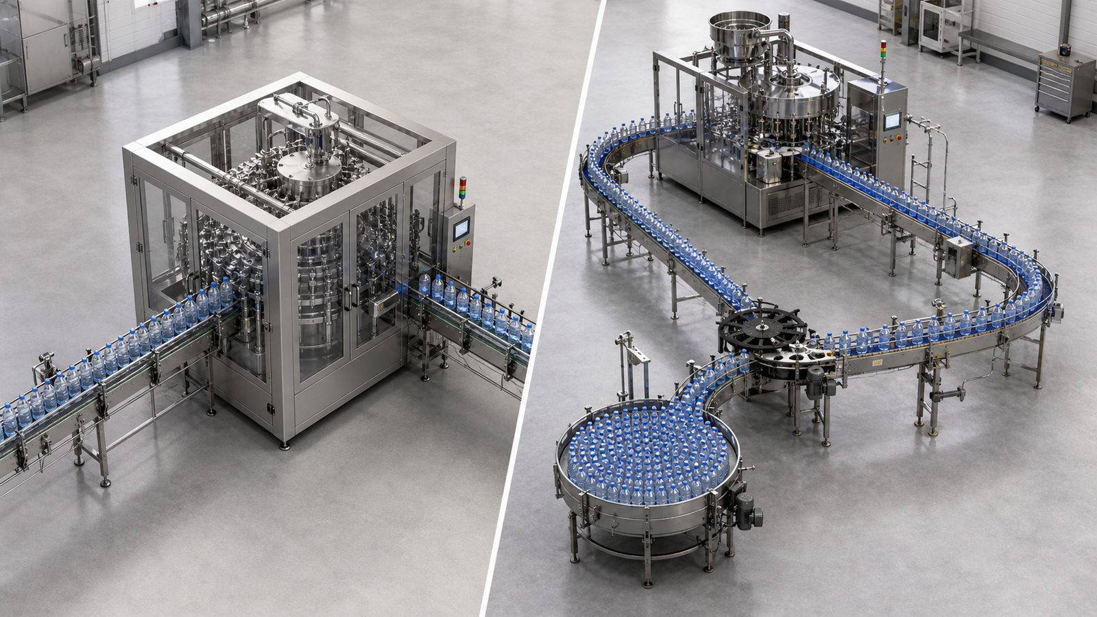
Floor space is more than the machine outline on a quotation. Include operator aisles, opened guards, change-part carts, cap loading, material staging, reject access, maintenance pull space and electrical-panel clearance. A compact frame that cannot be serviced from the available aisle is not truly space-efficient.
Monoblocks reduce unsupported travel between fill and closure. This is valuable for small, unstable or open containers, foaming products, volatile liquids and clean applications where a short exposure path helps control contamination. Shared star-wheel or turret handling can also reduce bottle-to-bottle contact.
Separate machines add transfers, but well-designed neck guides, side belts, timing devices and accumulation tables can make those transfers robust. They may be preferable when the filled container needs an intermediate check, settling time, gas treatment or manual intervention before capping.
Ask both suppliers for a scaled layout showing:
- Machine and conveyor outlines with all guards closed and open.
- Operator, cleaning and maintenance access.
- Product, component and reject flow.
- Change-part storage and movement.
- Utility drops, drains and cable routes.
- The longest component that must be removed for service.
Output, buffering and line-level OEE
Nominal cycles per minute are not the same as sustained good output. Line performance is affected by micro-stops, cap-feed interruptions, product replenishment, changeovers, cleaning, quality holds and reject rates. ISO 22400 provides an industry-neutral framework for manufacturing KPIs, while OMAC’s PackML guidance promotes consistent machine states and data that simplify integration and troubleshooting.
In a monoblock, one control system can synchronize the fill and cap stations and associate rejects with the correct process event. There is no inter-machine buffer, so a cap-feeder problem can immediately stop filling. The advantage is a short loss path and a single event history; the trade-off is that the shared block has one production state.
In a modular line, accumulation can decouple short disturbances. If the capper pauses for a minor adjustment, the filler may keep running until the buffer is full. This does not eliminate downtime; it changes when and where the loss appears. The buffer must be sized from the expected stop duration, line rate and container stability, not selected as an arbitrary conveyor length.
For a fair comparison, request a loss model with the same definitions:
| Loss question | Evidence to request |
|---|---|
| What is the guaranteed good-output rate? | Defined product, package, test duration and reject rules |
| What stops the full line? | Cause-and-effect matrix and machine-state diagram |
| How are micro-stops recorded? | Alarm history, reason codes and line-report example |
| Can a short capper stop be absorbed? | Accumulation capacity and tested stop/restart sequence |
| How are rejects traced? | Reject logic for no-fill, no-cap, bad torque and inspection failures |
| What is excluded from availability? | Agreed planned-stop and changeover definitions |
Avoid assuming an OEE percentage before production data exists. Use FAT results to validate cycle logic and site acceptance data to establish the actual baseline.
Changeover and multi-format flexibility
A monoblock can simplify changeover because one recipe coordinates container handling, filling and capping. It can also make changeover more interdependent: one new bottle may require a complete star-wheel set even if the filling nozzles are unchanged. The buyer should review the full format matrix, not only the current bottle.
Separate machines allow different scopes. A bottle may run on the filler with only guides and nozzle spacing changes, while the capper requires a new chuck, stabilizer and feeder track. This can reduce the cost of some future formats, but it creates two procedures and more opportunities for mismatched settings.
For each planned format, list bottle dimensions, material, stability, fill volume, product viscosity, cap type and target rate. Then require a changeover matrix showing parts, tools, adjustments, recipe parameters and first-good-container checks. A claimed “tool-less changeover” should still define which parts are replaced and how their correct positions are verified.
Maintenance, cleaning and fault isolation
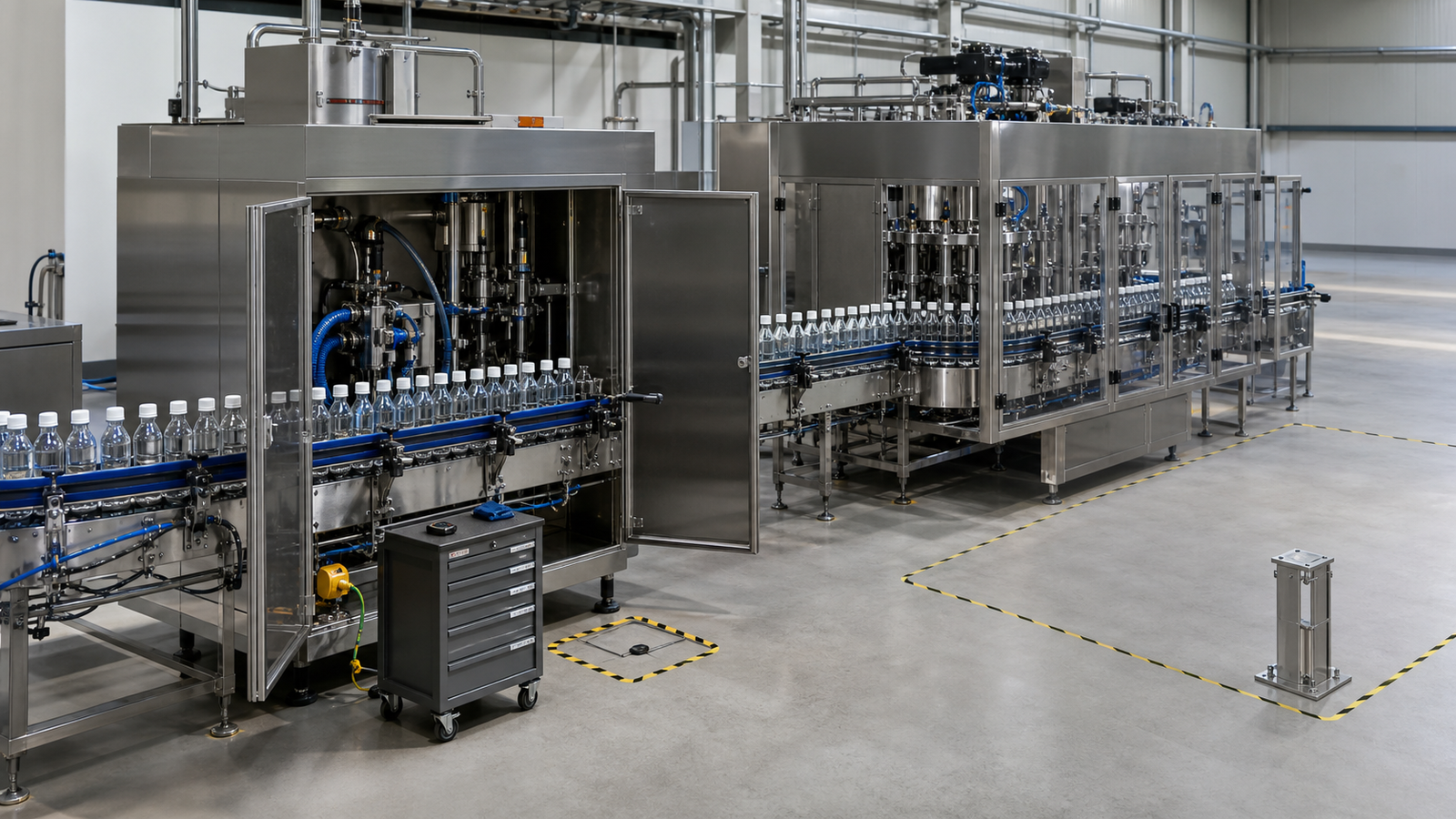
Monoblocks concentrate hardware. This reduces duplicate guarding and conveyors, but access to pumps, valves, capping heads and star wheels can be tighter. Review service tasks in the 3D layout or on a similar machine. Confirm that product-contact parts can be removed without disturbing qualified capper settings.
Separate machines provide clearer mechanical boundaries. Technicians can isolate the filler or capper, and a future replacement may be possible without rebuilding the other process. The price is more motors, sensors, conveyor wear parts and control interfaces.
For regulated or hygiene-sensitive work, cleanability is a design input. Product-contact surfaces, drainability, material compatibility, protection of exposed containers and change-control documentation should be reviewed separately from the layout decision. The pharmaceutical-industry solution page is a useful route for projects that need controlled container and component handling; cosmetic producers can use the cosmetic-industry equipment hub for product- and package-specific line options.
Capex, lifecycle cost and expansion
Do not compare quotations using base machine price alone. Use a common boundary and separate one-time investment from recurring cost.
| Cost driver | Monoblock question | Separate-line question |
|---|---|---|
| Equipment scope | Are cap feeder, inspection and reject included? | Are conveyors, line control and accumulation included? |
| Installation | How many utilities and field connections are required? | Who owns mechanical and controls integration? |
| Floor and room | Does the compact layout avoid a room expansion? | Is extra aisle and accumulation space available? |
| Change parts | Is a complete handling set required per format? | Which parts are shared across machines? |
| Downtime risk | What is the recovery plan for a shared-block failure? | What failures can buffers isolate, and for how long? |
| Maintenance | Are service access and critical spares practical? | How many additional conveyor and interface components exist? |
| Future capacity | Can heads or stations be added? | Can one machine be upgraded without replacing the other? |
A lifecycle comparison should include changeover labor, cleaning time, expected spares, planned maintenance, training, format additions and the cost of lost production. Use ranges and documented assumptions rather than confidential or generic machine prices.
Best-fit decision scenarios
Choose a monoblock when
- The bottle and closure family is stable and well defined.
- The production room is constrained or container travel must be minimized.
- Open or unstable filled containers should be capped immediately.
- One supplier will own the combined process guarantee and reject logic.
- Future capacity can be met within the monoblock’s station and feeder limits.
Choose separate machines when
- The plant runs diverse bottle, cap or filling technologies.
- Independent inspection or settling is required between fill and cap.
- Short stops should be absorbed through accumulation.
- The project is phased or must reuse existing equipment.
- Independent maintenance and future upgrades have high business value.
Consider a hybrid layout when
A compact fill-and-plug block can be followed by a separate capper, or filling and capping can remain independent while sharing a controlled enclosure and line control. Hybrid designs are useful when one transfer is critical but another process needs buffering or independent access.
RFQ questions that expose the real difference
- What exact product, bottle, cap and output assumptions support the proposal?
- Which operations, feeders, inspections and reject systems are included?
- What is the scaled operating and maintenance footprint?
- How does a filler, capper or feeder fault affect the rest of the line?
- What accumulation exists, and what disturbance duration can it absorb?
- How are machine states, alarms and production data exchanged?
- What parts and settings change for every planned format?
- How are rejected containers tracked and positively removed?
- What FAT endurance run and good-output criteria will be witnessed?
- What expansion path is technically supported, not merely described as possible?
Frequently asked questions
Is a monoblock always faster than separate machines?
No. Sustainable output depends on the slowest process, feeders, changeovers, faults and quality losses. A monoblock can reduce transfer delays, while separate machines can use buffering to absorb short stops.
Does a monoblock always cost less?
Not necessarily. It may reduce conveyors, guards, controls integration and floor cost, but dense engineering and format-specific handling can increase machine and change-part cost. Compare identical scope and lifecycle assumptions.
Can a monoblock handle multiple bottle sizes?
Yes, within its designed format envelope. Each bottle and cap still needs qualified handling, recipes and change parts. Large differences in diameter, height, stability or closure type can make a modular line more practical.
What happens if the capper stops on a monoblock?
The shared block normally stops, so filling pauses as well. Good controls should stop in a defined state, manage containers already in process and identify which units require rejection or reinspection.
How much accumulation should a separate line have?
Size it from the expected downstream stop duration, actual line rate, container stability and restart logic. More conveyor is not automatically better, especially for unstable or easily scuffed packages.
Which layout is better for pharmaceutical products?
Either can work. The decision must also address cleanability, enclosure strategy, product-contact path, container exposure, traceable rejects, validation and change control. These requirements may outweigh simple footprint comparisons.
Yes. Define machine states, speed references, block/starve signals, safety interfaces, alarms and production data. A consistent PackML-style state model can make machines from different suppliers easier to integrate and troubleshoot.
What should be tested at FAT?
Test every critical format with production-representative components, including starts, stops, replenishment, rejects, fault recovery, changeover and an agreed endurance run. Record good output, not only mechanical cycles.
Compare both concepts with your actual package
The most useful proposal is a side-by-side engineering comparison based on the same product and package data. King Pack can develop monoblock and modular concepts around your fill range, bottle and cap samples, target good-output rate, room layout, cleaning approach and future-format plan.
Send product properties, container drawings or samples, closure details, required output and an accurate floor plan. The project team can return two scoped layouts with included operations, change parts, controls boundaries, FAT criteria and an expansion path so the decision is based on total production risk rather than machine labels.
