 Skip to content


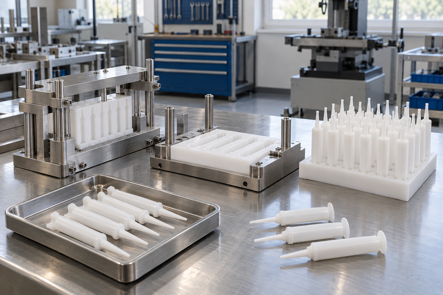
AI-generated illustration: control physical format parts and verify changeover setup.
Introduction
An intramammary filling line may handle more than one barrel, plunger or cap format, but a format change is never only a recipe selection. Nests, guides, star wheels, locators, cap tracks, sensors and inspection references may each be format-specific. When these parts are not identified and verified as a set, a line can start with an apparently correct setting while presenting the applicator incorrectly at a critical station.
This guide covers change-part control for veterinary intramammary applicator equipment. It is conditional engineering guidance: the final configuration, cleaning process and release requirements remain the customer’s responsibility.
The direct answer
Effective intramammary applicator change-part management identifies every format-specific item, links it to the component drawing revision, gives it a controlled storage location and verifies the installed setup before product is released. The objective is repeatable package presentation, not merely a faster changeover.
Request a format-change review
Send the applicator formats and component drawings you plan to run. We can identify the likely tooling, guide and verification points for a practical change-part list.
Define a format as a package, not a volume
Two applicators with similar nominal volume can have a different flange, barrel taper, cannula length, cap profile or plunger interface. Those differences can affect how a barrel enters a nest, where a filling nozzle meets it, how the cap feeder orients a closure and what a sensor sees. A format record should therefore identify the complete barrel, plunger and cap combination, not only “5 mL” or “10 mL.”
Build the controlled parts list
Start at the infeed and walk to cartoning. At each station, record whether a part, guide setting, sensor position, recipe or inspection reference is specific to the format. Include a unique part number, description, drawing revision, storage position and associated applicator format.
| Item | Why it may be format-specific | Verification before run |
|---|---|---|
| Nest or pocket | barrel body, flange or tip clearance | empty barrel sits fully and repeatably |
| Transfer guide | barrel width, orientation, cannula protection | no uncontrolled contact through transfer |
| Plunger tooling | stem/stopper interface and insertion height | location and final presentation confirmed |
| Cap track or seating tool | cap geometry and engagement | correct orientation and visual seating |
| Inspection reference | expected package appearance | approved visual sample available |
Store parts so errors are visible
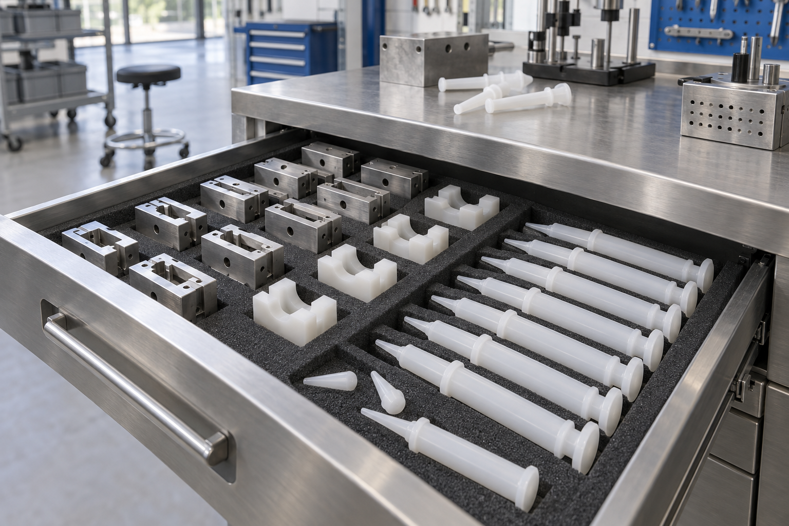
AI-generated illustration: organised storage helps maintain the identity and condition of change parts.
Mark the part and its storage location with a durable, readable identifier. Store matching sets together where possible, but do not rely on colour alone. A kit should include the setup sheet, its drawing revision and any special fasteners or gauges. Protect precision surfaces and label the orientation if a part can be installed more than one way.
Shipment inspection is a useful point to confirm that supplied change parts are listed, protected and linked to the tested format. This is not final production qualification; it creates a traceable handover for installation preparation.
Use a repeatable installation and first-piece check
The changeover instruction should say what is installed, which settings are controlled, what no-tool adjustments are permitted and which observations confirm readiness. Before filling product, run empty components through the relevant transfers. Then inspect the agreed first pieces after filling, plunger insertion and cap seating according to the customer’s procedures.
Record the operator, installed kit, component lot and any adjustment. If the setup requires repeated trial-and-error to achieve normal presentation, stop and investigate rather than turning an informal adjustment into the new standard.
Keep recipe control separate from tooling control
An HMI recipe can store selected settings, but it cannot prove that the correct nest or guide is physically installed. Conversely, the correct tooling cannot make an incorrect electronic setting safe. Treat the recipe, component identity and installed tooling as three linked checks. This is especially important after maintenance, a shift change or a component-supplier revision.
Build a changeover sequence around the actual stations
A format change should follow the package through the machine. Before removing tooling, clear the previous components and identify material held inside feeders, nests, transfer guides and discharge. Use the site’s line-clearance procedure for that material. Then isolate and prepare the equipment according to its supplied instructions before authorised work begins.
The tooling sequence should specify which item is removed, where it is stored and which replacement is installed. Include brackets, spacers, fasteners and gauges that are easily overlooked. A complete kit should enable a trained person to identify missing items before assembly starts. Leaving small format-specific pieces in an unmarked drawer makes the next change dependent on memory.
Verify seating and orientation mechanically
Before introducing product, use the approved empty component set to check the location established by the installed nest, guide and transfer. Confirm that the barrel rests at the intended datum, the fine tip remains clear and the plunger or cap approaches the package from the expected direction. An adjustment scale can support setup, but the actual component condition is the useful confirmation.
If a part can be installed in two orientations, make the correct orientation visible in the setup record. Where practical, the equipment design may include a locating feature that discourages incorrect installation. Discuss that option with the supplier instead of assuming every kit has error-proofing built in. The delivered features and their limits should be documented.
Verify sensors and recipes separately
A sensor bracket may need repositioning for a different barrel or cap. Confirm both its mechanical location and the event it detects. A component presence check cannot automatically establish seating or package function. Review the relevant recipe settings under the site’s approved access procedure and identify whether any parameter was changed during setup.
This separation helps troubleshooting. If a line stops after a format change, the team can check physical tooling, component identity and selected settings in a defined order. Repeatedly changing timing before confirming the kit can obscure the cause and make the final setup difficult to reproduce.
Use a first-piece record that follows the package

AI-generated illustration: an installed tooling check should use the approved package and machine instructions.
The first-piece review should include the points affected by the format change. Feeding and locating may be checked with empty components, while filling and final assembly need the customer’s agreed assessment method. Record the sample set, format kit, selected recipe and observations. The customer decides the sample quantity and production-release conditions.
| Station | Question after a change | Suitable observation |
|---|---|---|
| Barrel infeed | Is separation and orientation consistent? | Actual supplied component presentation |
| Nest or transfer | Does the barrel reach the intended datum? | Empty component seated with tip clearance |
| Filling presentation | Is package access aligned? | Nozzle and barrel condition under agreed checks |
| Plunger station | Is the assembly presentation correct? | Defined entry and end-position observation |
| Cap station | Is the right cap presented and seated? | Orientation and visible seating reference |
| Discharge | Is the completed package supported correctly? | Transfer and collection observation |
Use the result to establish a repeatable baseline. If the setup requires an adjustment, record it with the reason and approving role. A changeover record is most useful when it shows what was actually installed and observed, rather than simply marking a general box labelled completed.
Mid-article CTA — Send your format matrix
Share the barrel, plunger and cap combinations planned for your line. We can structure a format-to-tooling matrix for quotation, FAT and start-up preparation.
Protect tooling condition through storage and cleaning
Contact surfaces, locating features and precision edges should remain protected while parts are off the line. Store items so that heavy steel tooling does not bear against a delicate guide or polymer pad. Provide a clear location for suspect parts that need inspection. An apparently complete kit can still contain a worn or damaged item.
Cleaning requirements depend on the project and site procedure. The machinery supplier should identify relevant materials and disassembly instructions within the supplied scope; the customer should define the approved cleaning process. Avoid improvised chemical or abrasive treatment that changes the surface used for component support. After cleaning, check that moving or adjustable features return to their verified position.
Review wear at the contact features
When a new mark, unstable barrel or repeated feed fault appears, inspect the surfaces that locate and guide the package. The important observation is a change from the accepted condition, not an invented universal replacement interval. Use the maintenance system to determine whether a part remains serviceable, needs repair or should be replaced.
If the tooling is replaced, identify whether it is an equivalent item or a revised design. A revised locating feature can require another package-handling review even if the part still fits the machine. Keep drawing and kit records aligned so that an old setup photograph does not become the reference for a changed fixture.
Include changeovers in the factory-test scope
Factory testing can show how the formats included in the project are installed and verified. Agree which changeover will be demonstrated, what components are available and which checks are within scope. If only one format is supplied for the test, retain the untested format as an explicit open action.
Capture the actual kit identifiers, changeover steps and any adjustment needed with representative components. Observe whether the operator can identify the correct parts, access the stations and check the package state. A demonstration with known trial samples provides a starting point for installation preparation; it should not be described as proof for an unlimited format range.
At shipment inspection, compare packed tooling with the approved parts list. Protect items and include the records needed to match them to the tested format. At site startup, verify the delivered sets before introducing production components. This creates continuity between factory testing, shipment and the first site changeover.
Control revisions without multiplying unofficial setups
A changed barrel flange, cap shape or plunger interface may require a tooling review. Use the customer and project change process to identify the affected stations. Do not assume the same nominal volume means the previous kit remains suitable. The component drawing, supply presentation and observed route determine the practical impact.
Keep one current setup reference for each approved format and make obsolete instructions visibly unavailable for routine use. If a temporary adjustment is permitted, give it a defined owner and closure condition. Otherwise a successful short-term workaround can become an undocumented second standard used by only one shift.
The component-lot review guide helps distinguish changes in material supply from changes in equipment setup. Review both when the same kit behaves differently with a new component lot.
Send Your Requirements: Provide your format combinations and planned changeover workflow. Ask for a parts-list review that links package drawings, tooling and first-piece checks.
Purchase spares against the controlled kit list
A spare-part request should identify the equipment, format kit, part reference and revision. Add photographs of the contact feature when needed, but do not use a photograph as the sole identity of a replacement nest or guide. Parts that look similar may locate the applicator differently.
Specify interchangeability rather than assuming it
Ask whether the proposed spare replaces the original item directly or requires an accompanying bracket, spacer, setup adjustment or updated reference. Preserve the supplier’s answer with the kit list. If a replacement changes the contact geometry, review the affected package route before treating it as routine maintenance.
The same discipline applies when a second line is installed. Similar machine names do not prove that format parts can be exchanged between lines. Confirm the supplied interfaces and configuration. Mark line-specific items clearly enough that a technician can distinguish them during a busy changeover.
Keep repair history with the physical item
Where repairs are permitted, record what was changed and how the item was verified before returning it to service. A polished contact surface or replaced locating pin may require a package check even if the part retains its identity. Do not assume that removing visible damage establishes the original location condition.
Quarantine items that remain under assessment. Their storage should prevent accidental inclusion in a complete kit. The customer can decide which records belong in maintenance and which belong in format control, but the physical status must be unambiguous.
Make the tooling handover useful to another shift
A completed changeover should leave the next team with the component combination, installed kit, recipe reference and first-piece result. Include any temporary restriction or open adjustment question. These references support a review if handling changes later; they do not authorise continued operation outside the approved conditions.
For installation preparation, assemble the actual kit and instructions before the supplier visit. During shipment inspection, check the delivered parts against the agreed scope. During factory testing, identify which formats were demonstrated. Together these records distinguish a supplied spare from a proven setup and a proposed format from one actually reviewed.
FAQ
What should a change-part kit contain?
Include all format-specific nests, guides, tools, brackets and small accessories identified for the delivered scope, together with the current setup record. Verify completeness before installation.
Can a recipe prove that the right tooling is installed?
No. Recipe selection and installed tooling are separate checks unless a specific verified identification system is supplied. Confirm the component combination as well.
Can one tooling kit cover several applicator sizes?
Possibly, but only after the actual geometry and transfer behaviour are reviewed. Similar volume alone is not enough evidence.
How often should change parts be inspected?
Follow the customer’s maintenance system and inspect them when damage, wear, cleaning or an unexplained handling change is observed.
Is a factory-tested setup ready for all future components?
No. The record applies to the identified components and configuration. Material component changes should go through the customer’s change-control process.
Conclusion
Change-part management is a package-control discipline. A clear format definition, controlled kit, documented setup and first-piece check protect the applicator at the points where it is most likely to be mis-presented.
Discuss your format-change requirements
Contact Us: KINGPACK can review the component combinations and handling stations that affect change-part scope for an intramammary filling project. Contact us for a tooling matrix or trial plan.
—
