 Skip to content

Bottle cap torque is not a single machine setting that can be copied from another line. It is a validated operating window for a specific cap, liner, bottle finish, product, fill condition and storage cycle. Too little effective engagement can cause loose caps, leaks or loss of seal. Too much can damage threads, wrinkle liners, distort lightweight containers or create an unacceptable opening force.
The practical control strategy is to separate what the capping machine applies from what quality control later measures. Application torque describes the tightening input. Removal torque is the force required to open the package after a defined delay and conditioning history. The two are related, but material relaxation, liner compression, temperature, product contamination and thread friction mean they are not identical.

Quick answer: what does cap torque control?
Cap torque helps create consistent thread engagement and liner compression on continuous-thread closures. It does not prove seal integrity by itself. Establish an acceptable window through package testing, then verify the line with a calibrated torque instrument, a defined delay after capping, consistent sample conditioning and head-specific records.
Do not use a universal “torque per millimeter” rule as final acceptance. Closure-supplier guidance can provide a starting range, but the approved specification must be demonstrated with the actual package and required leak, opening, transport and shelf-life performance.
Application torque vs removal torque
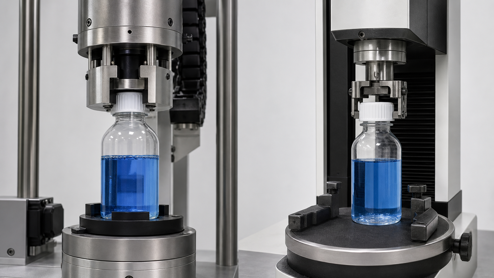
| Term | What it means | Where it is measured | Why it matters |
|---|---|---|---|
| Application torque | Rotational input used to tighten the closure | Capping head, instrumented spindle or laboratory application device | Controls initial engagement and liner compression |
| Immediate removal torque | Opening torque measured soon after application | Bench or automated torque tester | Useful for setup and short-term comparison |
| Aged removal torque | Opening torque after a defined time and environment | Conditioned package sample | Shows torque retention after relaxation and exposure |
| Breakaway torque | Peak torque required to start rotation | Torque test trace or peak reading | Relates to consumer opening and tamper-evident behavior |
| Running torque | Torque after rotation begins | Torque-angle trace | Can reveal thread drag, cocking or band interference |
ASTM D2063/D2063M-24 is an active quantitative method for measuring removal torque and torque retention of continuous-thread packages with manual equipment under controlled conditions. It is a test framework, not a product-specific pass/fail limit. Your protocol still has to define the package, conditioning, instrument, sample handling and acceptance window.
Why torque changes after capping
Polymer and liner relaxation
Plastic caps, bottle finishes and liners deform under load. After application, stress relaxes and the measured removal torque commonly changes. The amount and timing depend on material, geometry, liner construction and temperature. That is why a reading taken ten seconds after capping should not be mixed with a reading taken the next day.
Thread and surface friction
Mold release, cap coating, bottle-finish texture, moisture and product residue affect friction. A cap can receive the same machine input but reach a different axial load or removal torque when friction changes. Component-lot changes should therefore be part of the investigation when torque shifts without an obvious machine fault.
Liner compression and sealing-land condition
The liner needs sufficient and reasonably uniform compression against the sealing land. A nicked bottle lip, tilted cap, wrong liner thickness or product on the land can leak even when the removal torque is inside the historical range. Torque must be paired with visual and integrity checks.
Temperature and pressure history
Hot-filled packages cool and contract. Refrigerated, retorted or transported packages experience different dimensional and pressure conditions. Measure at defined process stages and simulate the intended distribution environment before approving the window.
Tamper-evident band behavior
Breakaway bridges or bands can add resistance to the first opening. If the test method does not separate thread breakaway from band fracture, results may be misinterpreted. Record the closure design and test endpoint.
How to establish a validated torque window
1. Freeze the package definition
Identify the cap drawing, resin, liner, bottle-finish drawing, bottle material, supplier and critical tolerances. Include the filled weight, fill temperature, product contact at the neck and any induction seal or secondary closure operation.
2. Define package performance requirements
The package may need leak resistance, vacuum or pressure retention, child-resistant performance, tamper evidence, distribution survival and a suitable opening force. Torque is one process variable supporting those outcomes.
3. Build a controlled test matrix
Apply several candidate torque levels across representative component lots. Use the same application method, downward force, capping speed and sample conditioning. Include realistic low and high process temperatures and worst-case component tolerances where practical.
4. Measure at fixed time points
Record immediate and aged removal torque at defined intervals. Do not combine different dwell times in one control chart. If the product has hot-fill, cooling, sterilization or refrigeration stages, add time points that reflect those conditions.
5. Test package outcomes
Perform the approved leak or integrity method, inspect liners and threads, evaluate opening and check cosmetic damage. A package that “passes torque” but fails a leak test is not acceptable.
6. Select the operating window
Choose a machine target and alert/action limits that provide margin from both package failures and process variation. The target does not have to be the midpoint if one failure mode has greater risk. Document the rationale and obtain quality approval.
7. Confirm on the production capping machine
Run production-representative bottles and caps through every head at the intended speed. Verify head-to-head consistency, stops and restarts, component replenishment and normal environmental conditions. Link every sample to the capping head or spindle where possible.
Torque test equipment and sampling plan
A manual torque meter is suitable for controlled development and routine checks when the fixture, operator technique and opening speed are standardized. Automated testers improve speed and can capture torque-angle curves, but the same conditioning and package definition are still required.
ASTM D3474-23 covers calibration and use of torque meters in packaging applications. A practical quality system should record instrument identity, calibration status, fixture, units, test direction, opening speed if controlled, time since capping, sample temperature, head number and result.
Use one unit system consistently. Never mix N·m, N·cm, lbf·in and kgf·cm in a worksheet without an explicit conversion. The reporting unit should match the approved package specification.
A risk-based sampling plan should answer:
- How many containers are checked at startup and after changeover?
- Is every capping head represented?
- What events trigger additional sampling: cap-lot change, jam, maintenance or alarm?
- Which reading is used for immediate process adjustment?
- Which aged sample confirms torque retention?
- What happens to product made since the last acceptable check?
For trend control, plot individual or subgroup results by head. A single line average can hide one weak chuck and one over-tight chuck that cancel each other numerically.
Loose-cap root causes and corrective actions

| Symptom | Likely causes | What to check first | Avoid this reaction |
|---|---|---|---|
| Low removal torque on all heads | Low machine target, cap/finish friction change, wrong recipe | Recipe, component lot, tester and delay | Raising torque before confirming the tester |
| Low torque on one head | Worn chuck, slipping clutch, spindle problem, height error | Head-specific samples and wear parts | Changing every head |
| Random loose caps | Cocked caps, unstable bottles, feed interruption, product on neck | Cap placement, bottle control and neck cleanliness | Increasing torque to compensate for misplacement |
| Torque drops during shift | Heat, wear, loose adjustment or material change | Time trend, machine temperature and part lot | Using only the shift average |
| Leak with normal torque | Damaged land, liner defect, contamination or incompatible package | Sealing surface and integrity test | Treating torque as a leak test |
Loose caps often begin before the tightening station. A cap that lands at an angle may cross-thread or seat incompletely. A flexible bottle that is not stabilized can rotate with the head. Product splashed onto the finish changes friction and liner contact. Correct placement and container control before increasing torque.
Over-tight caps, liner damage and bottle distortion
Excess input can strip plastic threads, deform a cap, wrinkle or cut a liner, fracture a glass finish or collapse a lightweight container. It can also produce opening forces that fail customer or usability requirements. The visible cap may look “secure” while the sealing system has been damaged.
| Defect | Possible torque-related mechanism | Confirmation check |
|---|---|---|
| Stripped thread | Cap or finish exceeds material/load capacity | Inspect thread profile and rotation after seating |
| Liner wrinkle or cut | Excess or uneven axial compression | Remove cap carefully and inspect full liner circumference |
| Bottle paneling/collapse | Downward load or chuck pressure deforms container | Observe capping in slow motion and measure bottle support |
| High opening force | Target too high, band drag or aged interaction | Separate thread, band and liner contributions |
| Stress cracking | Package material, chemistry and sustained stress interact | Component compatibility and conditioned aging study |
The correction may be lower torque, but it may also be better bottle support, a different chuck, corrected cap placement or a compatible liner. Diagnose the mechanism instead of treating every defect as a setpoint problem.
Machine adjustments by capper type
Chuck cappers
Review chuck insert condition, clutch or servo settings, head height, downward force and bottle stabilization. A worn insert can slip inconsistently. A head set too low can add unwanted top load even when rotational torque appears correct.
Spindle cappers
Check spindle-belt pressure, speed relationship, cap stabilizer, bottle side belts and final tightening spindle. Spindles should contact the cap consistently without distorting the bottle. One worn belt can create a position-dependent problem.
Servo cappers
Servo systems can record torque, angle or position signals, but the signal is not automatically equivalent to laboratory removal torque. Correlate the machine signature with package test results and protect approved recipes with access control.
ROPP, press-on and crimp closures
These closures are controlled by forming force, geometry, pressure or crimp dimensions rather than conventional screw application torque. Use the correct closure-specific tests. The ROPP capping machine guide explains why formed aluminum closures require thread and tuck-under verification.
For broader mechanical setup, use the capping-machine adjustment guide. Keep this page as the torque-control reference and the older page as the mechanical troubleshooting companion.
Preventive controls and records
- Approve cap, liner and bottle drawings and suppliers.
- Protect validated recipes and record changes.
- Verify the tester before use and maintain calibration traceability.
- Standardize the delay, temperature and opening method.
- Sample every head at startup, changeover and defined intervals.
- Trend results by head, component lot and time.
- Pair torque checks with cap-height, visual and integrity checks.
- Define line-stop, segregation and investigation rules.
- Inspect chucks, inserts, belts, clutches and bottle supports on schedule.
- Revalidate after a material, liner, finish, capper or process change.
The capping station should be reviewed as part of the complete filling and capping line. Fill level, neck contamination, conveyor handling and upstream timing can all change closure performance.
Frequently asked questions
What is a good bottle cap torque?
There is no universal value. Start with closure-supplier guidance, then validate a package-specific application and removal-torque window against leak, opening, storage and distribution requirements.
Why is removal torque lower than application torque?
Material stress relaxation, liner compression, friction and conditioning can change the measured value after capping. That is normal behavior, but the acceptable retention must be demonstrated and monitored.
How soon after capping should torque be tested?
Use fixed, documented time points. An immediate reading helps setup; an aged reading shows retention. The correct intervals depend on the package and process, so do not mix different delays in one trend.
Does the torque tester need calibration?
Yes. Use a defined calibration and verification program, suitable fixtures and traceable records. Confirm the instrument range and resolution are appropriate for the package.
Can torque testing replace leak testing?
No. Torque is a process measurement. Seal integrity also depends on the liner, bottle land, contamination, component compatibility and environmental history.
Why does one capping head produce loose caps?
Likely causes include a worn chuck, slipping clutch, spindle wear, height error or head-specific bottle control. Sample by head before adjusting the complete machine.
Why do caps become harder to open after storage?
Material interaction, temperature, liner adhesion, band behavior and product exposure can alter opening force. Use conditioned aging studies to identify the mechanism.
Should operators increase torque when a leak appears?
Only after confirming the leak is caused by insufficient engagement or liner compression. First inspect the cap, liner, finish, neck cleanliness, tester and placement. More torque can worsen damage.
Turn torque data into a stable capping process
If your line shows leaks, loose caps, high opening force or head-to-head variation, send King Pack the closure and bottle drawings, physical samples, current torque records, fill condition and target speed. The engineering review can compare package behavior with chuck or spindle condition, bottle control, cap placement and the approved test method.
The goal is not to find the highest torque the package will tolerate. It is to establish the lowest-risk operating window that consistently produces an intact seal, acceptable opening and stable production across normal component and process variation.
