 Skip to content

A ROPP capping machine does not simply tighten a ready-made screw cap. It presses an unthreaded aluminum shell onto a compatible bottle finish, then uses forming rollers to create the thread profile and tuck the lower skirt beneath the bottle’s locking ring. The result is a fitted closure with a pilfer-proof or tamper-evident band.
This distinction matters when specifying a line. The cap, bottle finish, plunger, thread rollers and tuck-under rollers must work as one qualified set. A capper selected only by nominal cap diameter can produce shallow threads, skirt wrinkles, broken bridges, spinning caps or damaged bottles when the cap height, aluminum temper, liner or neck geometry changes.

Quick answer: what does a ROPP capper do?
A ROPP capper places an aluminum closure over a specially designed bottle neck, holds the cap axially with a plunger, rolls the cap skirt into the bottle’s thread profile and forms the tamper-evident band beneath the transfer or locking ring. “ROPP” means roll-on pilfer-proof. The thread is formed during capping rather than molded into the cap beforehand.
Choose a ROPP system when the product and package require a formed aluminum closure, a defined opening experience and visible tamper evidence. Before ordering, qualify the exact cap drawing, bottle-finish drawing, liner, product, fill condition and required output with physical samples.
ROPP closure anatomy at a glance
| Package element | Function during capping | What the buyer must define |
|---|---|---|
| Aluminum cap shell | Deforms around the bottle finish | Diameter, overall height, skirt thickness, temper, coating and dimensional tolerances |
| Liner or sealing element | Creates the product seal at the bottle land or lip | Material, product compatibility, compression range and processing temperature |
| Cap top panel | Receives axial load from the plunger | Panel profile, embossing, decoration and permitted cosmetic marks |
| Thread-forming zone | Is rolled into the bottle’s helical thread | Available skirt height, bottle thread geometry and required thread depth |
| Bridges or score line | Connect the cap body to the tamper band before opening | Bridge count or pattern, breaking behavior and inspection criteria |
| Tamper-evident band | Is tucked beneath the bottle locking ring | Band height, ring geometry, tuck position and opening performance |
| Bottle finish | Acts as the forming mandrel for the cap | Neck material, drawing, tolerances, top-load strength and surface condition |
The closure supplier’s drawing and bottle-finish drawing are the starting documents. Krones’ current closure specification notes that original cap samples are needed to design closure-dependent parts and that different ROPP height formats require matching head geometry. The practical lesson is simple: “28 mm ROPP” is not a complete machine specification.
How a ROPP capping machine works step by step
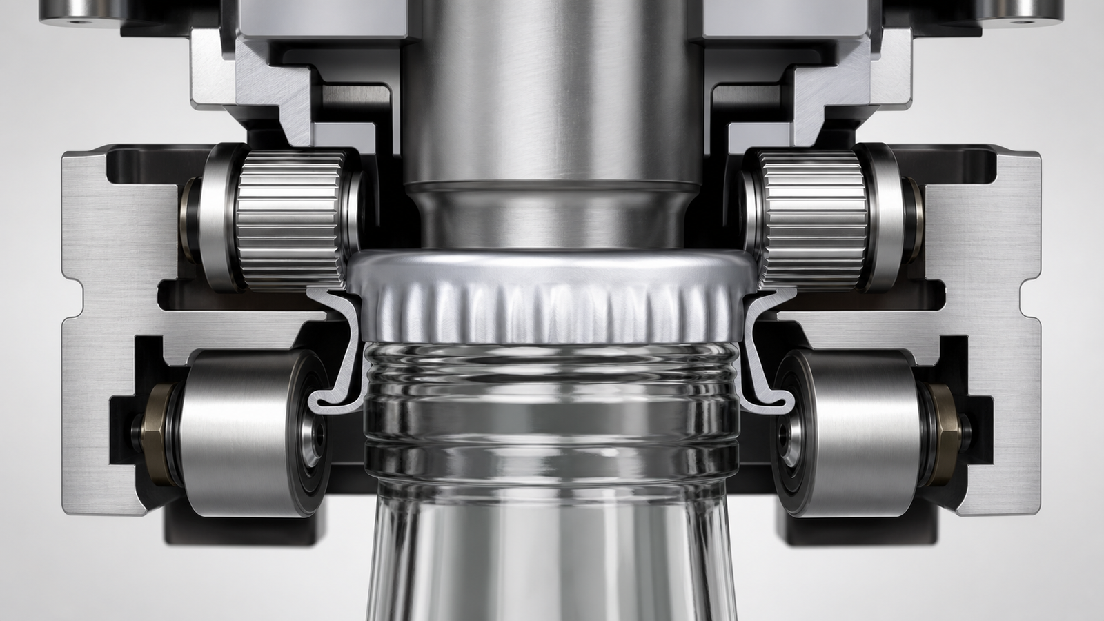
1. Bottles and caps arrive in a controlled position
Filled bottles are spaced by a timing screw, gate, star wheel or indexing mechanism. A cap sorter or elevator orients aluminum shells and sends them to a chute or pick-and-place station. The cap must land squarely over the bottle finish. A tilted shell can be permanently creased before the forming rollers reach it.
Container handling should be evaluated together with the filling and capping line. Product on the sealing land, foam at the neck or unstable bottle spacing can undermine capping even when the head itself is correctly adjusted.
2. The plunger centers and loads the cap
The capping head descends, and a plunger or pressure pad seats the shell against the bottle land. This axial force compresses the liner and keeps the cap from lifting while the rollers work. Too little force can create poor sealing contact or unstable forming. Excess force can distort the cap, damage the liner or overload a lightweight bottle.
The plunger must also suit the top-panel design. Deep embossing, decorative relief or an unusually shaped cap may require a dedicated contact profile to avoid marking the closure.
3. Thread rollers form the cap around the bottle thread
Thread rollers move inward against the cap skirt while the head rotates relative to the bottle. The bottle finish acts as a mandrel: the aluminum conforms to the helical thread below it. Roller radius, lateral force, vertical position and path determine whether the new thread is deep and smooth enough for secure retention and predictable opening.
Krones’ closure specification warns that excessive thread-roller side force can cut into the closure or damage the bottle. For that reason, generic pressure settings should not be copied from another cap without a sample trial.
4. Tuck-under rollers form the pilfer-proof band
Separate rollers turn the lower skirt beneath the bottle’s locking ring. This creates the band that remains on the bottle or visibly separates when the cap is first opened, depending on the closure design. The tuck must be continuous and correctly positioned without crushing the bridges or wrinkling the band.
Thread and tuck-under rollers have different jobs. A cap may look tight at the top but still fail tamper-band inspection if the lower rollers are high, low or uneven.
5. The head releases and the finished closure is inspected
The head rises or the bottle leaves the rotary turret. Inspection can include cap presence, cap height, skirt and band profile, bridge condition, top-panel appearance and opening performance. Some checks can be automated with vision or height sensors; others require sampled destructive tests.
Capping-head and roller configuration
A ROPP head normally combines a plunger with dedicated thread-forming and tuck-under roller arms. The exact number and geometry of rollers vary by head design, cap size and application. More rollers do not automatically mean better quality; the head must provide sufficient forming contact while respecting the cap and bottle tolerances.
The main configuration questions are:
- Does the head match the cap’s diameter and standard, high or extra-high skirt format?
- Can the plunger accommodate embossing or decoration without visible marking?
- Are thread and tuck-under rollers independently adjustable and positively locked?
- Can format parts be replaced without losing qualified reference positions?
- Are roller bearings and pivots protected from product, water and cleaning chemicals?
- Can each head or station be identified during quality sampling?
For a pharmaceutical project, cleanability and controlled component handling can be as important as output. The pharmaceutical-industry filling solution provides the broader line context; the user requirement specification should still state the site’s material, cleaning, documentation and qualification needs.
Where ROPP cappers are used
ROPP closures are used on compatible glass, metal and plastic containers in beverage, food, pharmaceutical, cosmetic and chemical packaging. Common examples include wine and spirits bottles, edible-oil bottles, syrups, oral liquids and specialty chemicals. Suitability is determined by the complete packaging system, not the market label.
| Application condition | Why ROPP may be considered | Qualification focus |
|---|---|---|
| Glass beverage bottle with aluminum closure | Premium appearance, resealability and visible tamper evidence | Glass finish tolerance, cap decoration, liner and opening performance |
| Pharmaceutical syrup or oral liquid | Controlled closure geometry and tamper-evident presentation | Product compatibility, clean handling, seal integrity and documented qualification |
| Edible oil or food bottle | Metal closure and consumer-visible band | Neck cleanliness, liner compatibility, leakage and distribution testing |
| Chemical bottle | Compatibility and defined opening evidence | Product vapor, cap coating, liner, corrosion and workplace requirements |
| Lightweight plastic container | Possible only with a suitable ROPP finish and support | Neck stiffness, top load, heat history and deformation during forming |
A ROPP cap is not interchangeable with a conventional pre-threaded continuous-thread cap. It also differs from the crimp seal used on many injection vials. If a project uses more than one aluminum closure family, identify each one by drawing and sample rather than by color or nominal diameter.
Single-head, multi-head and rotary ROPP machines

Single-head indexed capper
A single-head machine stops or indexes one bottle beneath the capping head. It is often appropriate for lower outputs, pilot production, frequent manual support or a limited format range. Its advantages can include simpler access and lower initial cost. Its sustainable speed is constrained by bottle positioning, head descent, forming time and discharge.
Multi-head inline or indexed system
Multiple heads increase output by processing more than one bottle per cycle or by distributing cycles across stations. The line needs reliable pitch control and consistent bottle presentation. Sampling must identify the producing head so one worn or misadjusted station is not hidden by an acceptable overall average.
Rotary turret capper
A rotary ROPP capper carries bottles through multiple continuously moving heads around a turret. It is the normal starting point for higher outputs and integrated beverage lines. The buyer should evaluate transfer stars, neck or base handling, cap-feed capacity, reject tracking and access for changeover and maintenance—not only the advertised bottles per hour.
Sustainable accepted output should be demonstrated with the actual closure and container. Catalog figures from another cap size or bottle geometry are not a performance guarantee.
Critical process parameters and defect diagnosis
| Defect | Likely process areas | What to check first |
|---|---|---|
| Shallow or incomplete thread | Thread-roller force, radius, height, bottle thread or cap temper | Compare drawings and samples; inspect every head; verify roller lock positions |
| Cut, torn or heavily marked skirt | Excess roller pressure, damaged roller, hard contact or incorrect cap material | Inspect roller surface and bearing; reduce only within validated limits |
| Wrinkled tamper band | Tuck roller height, angle, skirt length or cap ovality | Check cap roundness, bridge position and full-circumference tuck |
| Broken bridges before opening | Excess tuck, cap handling damage or unsuitable score pattern | Examine incoming caps and feeder contact before changing the head |
| Cap spins on bottle | Insufficient thread depth, finish mismatch, contamination or liner problem | Check formed profile, neck cleanliness and component dimensions |
| Leakage | Liner mismatch, inadequate axial load, damaged land or product on finish | Inspect sealing surface and liner compression; perform package integrity tests |
| Bottle neck damage | Excess top load or side force, poor centering or weak finish | Confirm bottle specification, support and head alignment |
| Wide variation between samples | One head out of condition, cap-lot variation or unstable handling | Record results by head, cap lot, bottle lot and time |
Do not use opening torque alone to judge a ROPP package. Opening force is affected by the formed thread, liner, bridge design, storage time, temperature and product contamination. Combine visual profile checks with leakage or integrity tests and the closure supplier’s approved methods.
The existing King Pack article on capping-machine adjustment methods is a useful troubleshooting companion. This guide remains focused on ROPP technology selection, sample qualification and buying decisions.
Change parts, maintenance and validation
The format package can include plungers, thread rollers, tuck-under rollers, cap chutes, bottle guides, star wheels and recipes. Ask the supplier to list which parts change for cap diameter, cap height, bottle diameter and bottle height. “Tool-free” should be defined as a demonstrated procedure rather than a marketing label.
Routine maintenance should cover roller surfaces, bearings, pivots, return springs, plunger faces, head lift mechanisms, cap tracks and bottle-handling parts. A roller that does not move freely can create a defect that appears only on one head. Use numbered heads and retain inspection records so maintenance is linked to quality results.
For validation, establish approved component drawings and representative tolerances. Test incoming cap and bottle lots, startup and steady-state production, the slowest and fastest line conditions, changeover, stops and restarts. For regulated or high-risk products, define installation, operational and performance qualification evidence in the contract.
Factory acceptance test for a ROPP capper
| FAT item | Evidence to record | Acceptance basis |
|---|---|---|
| Component coverage | Each cap, liner and bottle drawing plus representative samples | All contracted formats run with listed parts and recipes |
| Formed thread | Profile, depth or closure-supplier check and opening test | Meets the approved package specification on every head |
| Tamper band | Tuck position, bridge condition and first-opening behavior | Consistent visible tamper evidence without premature bridge damage |
| Seal performance | Leakage, vacuum, pressure or other package-specific method | Meets the pack owner’s validated limit and test timing |
| Sustainable output | Accepted bottles per minute over agreed duration | Achieves the quoted rate with normal feeding and handling |
| Fault challenge | Missing cap, tilted bottle, cap-feed low level and guard opening | Correct alarm, stop or reject response is demonstrated |
| Changeover | Parts, settings, elapsed time and first-good-bottle verification | Trained operator completes the approved procedure |
| Documentation | Drawings, manuals, parts list, certificates and training records | Agreed documents supplied at the correct revision |
Supply enough production-representative caps and bottles for an endurance run. Krones’ published closure guidance likewise emphasizes original sample material and final testing. If the supplier receives only a perfect hand-picked sample, the FAT may not reveal real lot-to-lot variation.
ROPP capper buying checklist
Before comparing quotations, confirm the following:
- The exact cap drawing, height format, liner and bottle-finish drawing are identified.
- Production samples from each planned component supplier have been tested.
- The cap feeder handles decoration and thin aluminum without dents or abrasion.
- The plunger, thread rollers and tuck-under rollers are included for every format.
- Bottle support prevents neck damage and accommodates the real filled weight.
- Acceptance criteria cover thread, band, bridges, appearance, seal and opening.
- Quality samples can be traced to the individual capping head.
- The output guarantee states the cap, bottle and test duration.
- Changeover parts, recipes, tools and expected time are listed.
- Cleaning, guarding, utilities, training, FAT, installation and service are in scope.
Frequently asked questions
What does ROPP stand for?
ROPP stands for roll-on pilfer-proof. Rollers form an aluminum closure around a compatible bottle finish and create a tamper-evident band below the locking ring.
Is a ROPP cap already threaded before application?
Normally the aluminum shell is not supplied with the finished bottle thread. The capping head forms that thread against the bottle finish during application. The lower band is formed in the same capping cycle.
What is the difference between ROPP capping and screw capping?
Conventional screw capping applies controlled rotation to a pre-threaded cap. ROPP capping deforms an aluminum shell to create the thread and band on the bottle. The heads, quality checks and change parts are therefore different.
Can one ROPP head run every 28 mm cap?
No. Caps with the same nominal diameter can differ in height, skirt profile, liner, temper, decoration and tamper-band position. The head and rollers must be qualified against the exact closure and finish.
Can a ROPP capper run plastic bottles?
It can run a plastic bottle only when the container has a suitable ROPP finish and enough neck strength for axial and radial forming forces. Physical trials should confirm deformation, sealing and opening performance.
How is ROPP closure quality checked?
Typical checks include cap height, formed-thread profile, tuck-under position, bridge condition, cosmetic appearance, opening behavior and a package-specific leak or integrity test. Results should be associated with individual heads.
What causes a ROPP cap to spin?
Possible causes include shallow forming, an incompatible bottle finish, cap or bottle dimensional variation, product on the neck, liner issues or a worn head. Inspect components and head-specific results before changing pressure.
What samples are needed for a quotation?
Send the cap and liner specification, bottle-finish drawing, filled-bottle weight, product information, target output and physical component samples. Include the worst-case tolerances and all suppliers planned for production.
Turn cap and bottle samples into a qualified specification
A successful ROPP project begins with the package, not the machine catalog. The cap shell, liner, bottle finish and opening requirement define the head; the desired output defines how many controlled stations and how much feeding capacity the line needs. Qualification then proves that every head forms the same acceptable closure across normal component variation.
Send King Pack your bottle-and-cap drawings and representative samples for roll-profile and package testing. The project team can review the required head, output, change parts and integration with the wider filling and capping process before a final machine configuration is proposed.
