
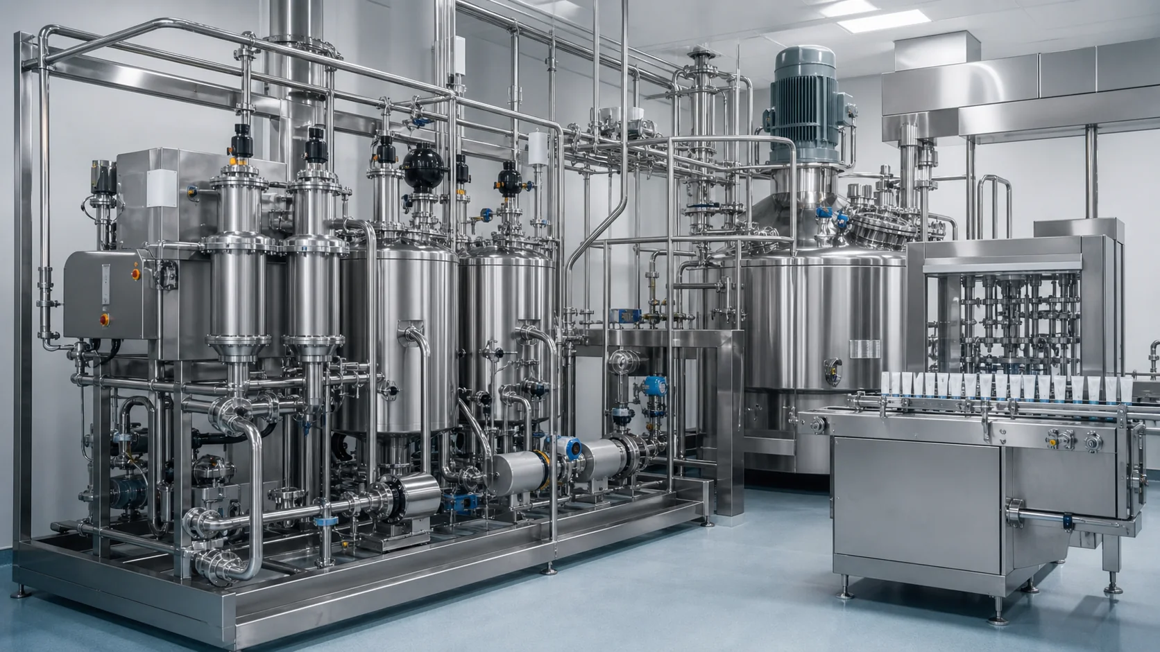
CIP design for an emulsifying and tube filling line begins with a boundary map, not with a cleaning skid quotation. A vacuum mixer may be cleanable in place while its scraper seals, powder port, sampling valve or homogenizer require special attention. Transfer piping may support circulated cleaning, yet the filler nozzle, dosing cylinder, hopper accessories and tube-format parts may still require removal and cleaning out of place (COP).
Quick answer: divide every product-contact surface into CIP, COP or manual-clean categories. Define the product soil and cleaning target, then design supply, spray coverage, flow path, return, drainability, instrumentation and recipes around that boundary. Automation improves repeatability only when the equipment is physically cleanable and verification proves that the selected cycle reaches the defined surfaces.
Quick CIP boundary map
| Equipment area | Possible cleaning mode | Main design question | Verification evidence |
|---|---|---|---|
| Main emulsifying vessel | CIP with fixed/rotary spray devices | Are roof, wall, bottom, agitator and shadow areas covered? | Riboflavin/coverage test plus rinse and residue results |
| Homogenizer and recirculation | Circulated CIP, sometimes assisted/manual | Does cleaning solution pass through every product path? | Flow/pressure record and inspection of dismantled worst-case areas |
| Transfer pump and pipe | Circulated CIP | Is velocity adequate and is every branch drainable? | Return flow, temperature, conductivity and low-point inspection |
| Buffer tank | CIP if hygienically designed | Does its addition improve production enough to justify another circuit? | Coverage, drainability and validated recipe |
| Filler hopper and manifold | CIP/WIP depending design | Can all valves, seals and dosing chambers be exposed to solution? | Circuit test, rinse samples and component inspection |
| Nozzles, small hoses and format parts | Often COP or manual | Can parts be removed, identified and reassembled correctly? | COP procedure, parts list and inspection |
| Tube handling and sealing stations | External/manual cleaning | Are they outside the product path but exposed to splashes or dust? | Line-clearance and surface-cleaning checklist |
Define product soils and cleaning requirements
Cleaning requirements come from the formula family, manufacturing risk and site quality system. List oils, waxes, pigments, polymers, fragrances, active ingredients and preservatives. Identify soils that harden when cold, burn onto hot surfaces, swell seals, stain elastomers or resist water rinsing.
Define the objective for each changeover. A same-product campaign rinse, color change and high-risk product change may require different recipes and verification. State whether the target is visually clean, below an established residue limit, microbiologically controlled or suitable for a regulated validation program. The equipment supplier can support the cleaning design, but the manufacturer owns the acceptance rationale.
Use representative worst cases. The hardest-to-clean formula may not be the most viscous; a strongly colored or low-solubility ingredient can be more challenging. Select soils using risk and evidence rather than naming one universal worst product.
Specify water quality, chemical compatibility, maximum temperature, concentration and exposure time. GEA operating guidance emphasizes that cleaning agents must be suitable for the task and compatible with equipment materials. Confirm stainless steel, seals, scraper materials, hoses, sensors and pump components with the chemical supplier and equipment manufacturer.
Map the complete cleaning boundary
Draw the product path from raw-material ports through mixer, valves, pump, transfer line, buffer, filler hopper, dosing manifold and nozzle. Mark every branch, sample point, instrument, vent, drain, flexible hose and removable component. Then assign CIP, COP or manual cleaning and name the owner for each boundary.
Do not label the entire line “automatic CIP” when parts must be removed. A truthful boundary schedule prevents gaps and makes labor visible. It should state disassembly, cleaning location, inspection, drying, protected storage and reassembly for every COP item.
Separate product recovery from cleaning. Define how saleable product is pushed, pumped or drained before the pre-rinse and how the recovery step avoids air or foreign-material contamination. Reduced hold-up improves yield and reduces the soil load entering the cleaning system.
For King Pack equipment context, see the mirror-polished CIP/SIP cosmetic emulsifying mixer page. Project claims must still be tied to the actual mixer geometry and cleaning test.
Design spray-device coverage for the mixer
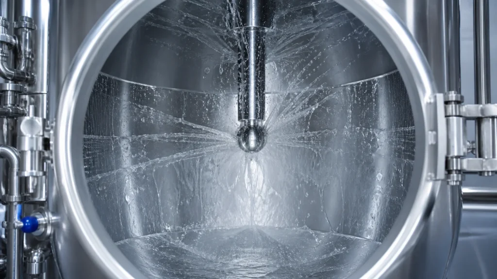
Tank cleaning requires mechanical action at every relevant surface. Select static spray balls, rotary spray heads or other devices from vessel diameter, internals, soil, available pressure and flow. Alfa Laval notes that rotary spray heads are offered with different spray patterns to suit vessel geometry; the installed pattern must be checked against actual obstructions.
Model and test shadow areas created by the anchor, wall scrapers, homogenizer, baffles, probes, ports and roof fittings. Rotating the agitator slowly during cleaning may expose surfaces, but only if the machine is designed and interlocked for that mode. Define the safe speed, spray interaction and seal protection.
The spray device needs a verified operating window. Record supply flow and pressure at the device, not only at the skid. A partially blocked nozzle or incorrectly positioned valve can reduce impact while the recipe timer continues normally.
Coverage testing demonstrates where cleaning solution reaches; it does not alone prove residue removal. Combine an agreed fluorescent coverage test or equivalent with visual inspection, rinse analysis, swabs where appropriate and product-specific verification.
Engineer transfer pipes, valves and return flow
Piping should be short, drainable and free of unintended dead legs. Slope routes to defined low points and place drains where the circuit can empty. Review valve bodies, instrument tees, sample points and bypasses. Every branch must have a defined flow path during each recipe phase.
Cleaning velocity depends on pipe size and soil. GEA literature notes that turbulent flow is important and cites about 2 m/s as a typical pipe target in one pump-system context, while also warning that viscous-product pumps may need a separate cleaning pump to reach the required flow. Use project calculations and supplier data rather than copying a number without context.
The return system must handle air, foam and elevation. A return pump may be required when gravity is insufficient. Monitor return flow or pressure so the recipe cannot claim success after a dry or poorly connected circuit.
Design valve sequencing to prevent cross-contamination between product, water, chemical and drain routes. For complex lines, flow panels or mix-proof valve matrices can automate routing. The valve state, feedback and failure response should be part of the FAT test.
Clean the filler product path without overstating CIP
The filler product path may include hopper, agitator, level probe, transfer inlet, dosing chamber, rotary valve, manifold, hoses and nozzles. Determine which components can be cleaned in position with sufficient flow and which must be removed. A smooth external machine frame does not prove internal cleanability.
For piston dosing, cleaning solution must reach both sides of product-contact valves and the complete cylinder stroke. For rotary or other pump systems, verify the cleaning position and rotational mode. Flexible hoses need compatible materials, controlled routing and inspection intervals.
Nozzles can contain shutoff mechanisms, suck-back cavities and small clearances that trap cream. Some designs can be circulated; others are more reliably disassembled and cleaned out of place. State the method in the URS and request a component drawing.
If the hopper is cleaned in place, verify spray coverage under the lid, around the agitator and at the outlet transition. Confirm that cleaning solution cannot enter electrical or tube-handling areas. Guarding and drain trays should control external splash.
The existing tube-machine CIP maintenance article provides maintenance context. This page defines the end-to-end cleaning boundary and evidence.
Identify tube-filler parts that remain COP
Tube holders, guides, orientation components and sealing tools are generally outside the product circuit, but they can receive product splashes and need manual cleaning. Product-contact nozzles, valves, hoses, seals and dosing parts may require COP depending on machine design.
Create a numbered parts list with photographs, materials and storage positions. The COP procedure should cover disassembly order, pre-rinse, detergent, mechanical action, rinse, inspection, drying, protection and reassembly. Avoid soaking incompatible seals or precision components beyond approved limits.
Use dedicated carts or racks so cleaned parts do not contact the floor or become mixed between formats. Include small parts and tools in reconciliation. A fully automated vessel cycle does not remove the need for disciplined line clearance and parts control.
Verify reassembly with keyed connections, part numbers, torque requirements or setup gauges. The first production batch should not be the test that reveals a missing seal or reversed valve component.
Improve recovery, drainability and return design
Product remaining in the mixer, outlet, pump, hose and nozzle increases yield loss and cleaning demand. Measure residual mass during trials. Optimize vessel bottom, outlet elevation, pipe slope, pump position and recovery sequence while protecting product quality.
Every CIP phase should end in a known destination: recovery, drain or reuse tank. Avoid pockets that retain diluted chemical and contaminate the next rinse. Check low points after the cycle and include drain-time limits in the acceptance protocol where important.
Air blows or pigging may improve recovery in some systems, but they add compressed-gas quality, pressure control and validation questions. Do not add them without a defined benefit and safe pressure boundary.
Return conductivity can help distinguish water, detergent and final rinse. Alfa Laval describes conductivity measurement as suitable for separating media and measuring cleaning agents in CIP equipment. Conductivity is an indirect control; it must be correlated with the actual chemical and temperature.
Build recipes around time, action, chemistry and temperature
A cleaning recipe normally combines pre-rinse, chemical wash, intermediate rinse, optional acid wash or sanitation, final rinse, drain and drying as required. Alfa Laval describes a comparable sequence and notes control of temperature, flow and detergent concentration in the return line. The correct steps and limits depend on the product and site program.
Record the variables that determine cleaning: time, mechanical action or flow, chemical concentration and temperature. Use permissives so exposure time starts only after required flow, temperature and concentration reach their limits at the defined point.
| Recipe parameter | Instrument or evidence | Typical failure to detect |
|---|---|---|
| Supply/return flow | Flowmeter or validated pump condition | Blocked spray device, wrong valve route, air-bound return |
| Temperature | Supply and critical return temperature | Heater fault, excessive loss, short exposure |
| Concentration | Conductivity correlated to chemical | Weak make-up, dilution or wrong recovery route |
| Exposure time | Recipe timer with permissives | Timer running before conditions are achieved |
| Drainability | Level/low-point check and drain time | Retained chemical or rinse water |
| Valve route | Command and position feedback | Cross-connection or uncleaned branch |
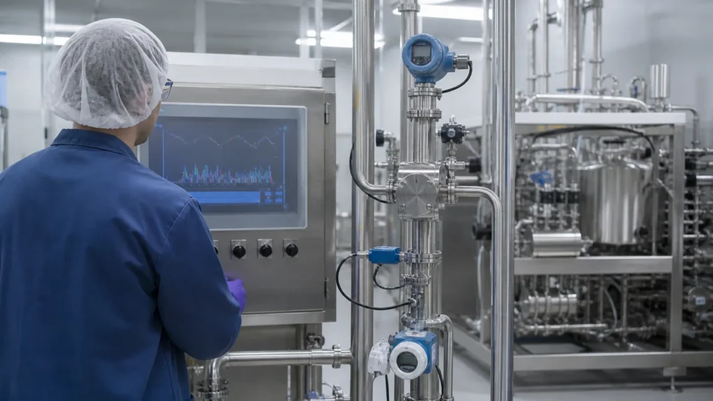
Store recipe version, equipment route, batch/product context, alarms and operator interventions. Automation should make exceptions visible, not allow the operator to acknowledge an alarm and still print a passing record.
Verify coverage, repeatability and cleaning results
Commissioning should prove hydraulic function before cleaning performance. Confirm pump direction, valve sequencing, spray-device flow, return capacity, heating, dosing, sensor calibration, alarms, interlocks and safe drain routing.
Perform coverage tests on the installed vessel and difficult components. Test worst-case agitator position, spray pressure and obstructions. Photograph results and document any manually cleaned exclusions.
Cleaning verification should follow the site risk assessment. It may include visual inspection, final-rinse conductivity or pH, total organic carbon, specific residue testing, swabs, microbiological sampling or another justified method. Sampling locations must target hard-to-clean areas rather than only convenient drains.
Repeat the cycle enough times to demonstrate consistency under defined conditions. Challenge product hold time and soil drying if these can occur in production. Record deviations and update the recipe or hardware before final approval.
GEA’s pharmaceutical CIP guidance emphasizes monitoring flow, concentration, temperature and wash time for repeatable and verifiable cleaning. Apply the same principle without claiming pharmaceutical validation where the project has not performed it.
CIP URS checklist and King Pack review
- Product families, soils and worst-case rationale
- Cleaning target and verification method for each changeover
- Complete boundary map with CIP, COP and manual items
- Product recovery and measured residual-volume target
- Vessel spray device, coverage and agitator cleaning mode
- Pipe diameters, slopes, low points, branches and return method
- Pump, valve and instrument cleaning positions
- Filler hopper, dosing path, nozzle and removable-parts scope
- Water, chemical, temperature and material-compatibility limits
- Recipe phases, permissives, alarms, reports and user roles
- Coverage, hydraulic, rinse/residue and repeatability tests
- FAT/SAT boundary and site validation responsibilities
King Pack can review the formula family, mixer, transfer route, buffer and tube filler layout to prepare a cleaning-boundary schedule. The proposal should clearly state which items are automated CIP, which require COP or manual cleaning, the required utilities and the verification evidence planned for FAT and site commissioning.
For the wider equipment map, see the King Pack cosmetic industry page. Send the equipment layout, product families, cleaning targets and available utilities for a project-specific CIP boundary review.
Frequently asked questions
Can an entire emulsifying and tube filling line be cleaned automatically?
Only if every product-contact component is designed for CIP. Many filler nozzles, dosing parts, hoses or format components still require COP or manual cleaning, which must be stated explicitly.
What proves that a mixer spray device has full coverage?
An installed coverage test can show wetted surfaces and shadow areas. It should be combined with product-specific residue or rinse verification because coverage alone does not prove soil removal.
Why is return flow important in CIP?
The return confirms that solution is circulating through the intended route and prevents the vessel or line from flooding. Insufficient return can reduce mechanical action and invalidate recipe conditions.
Is conductivity enough to verify a final rinse?
Conductivity is useful for detecting chemical concentration or media transitions, but it is indirect. The site must correlate it with the chemical, temperature and required residue endpoint.
Which tube filler parts are commonly cleaned out of place?
Depending on design, nozzles, shutoff parts, valves, hoses, dosing seals and small product-contact components may be removed. Tube holders and sealing tools are usually externally cleaned rather than part of the CIP circuit.
What should be tested during FAT?
Test valve routes, pumps, spray-device flow, return capacity, heating, chemical dosing simulation, sensors, alarms, interlocks, reports and documented coverage where the agreed factory setup permits it.
What information is needed for a CIP line review?
Provide product families, soil and hold-time risks, equipment drawings, pipe routes, cleaning targets, water and chemicals, available utilities, COP expectations and required verification documentation.