
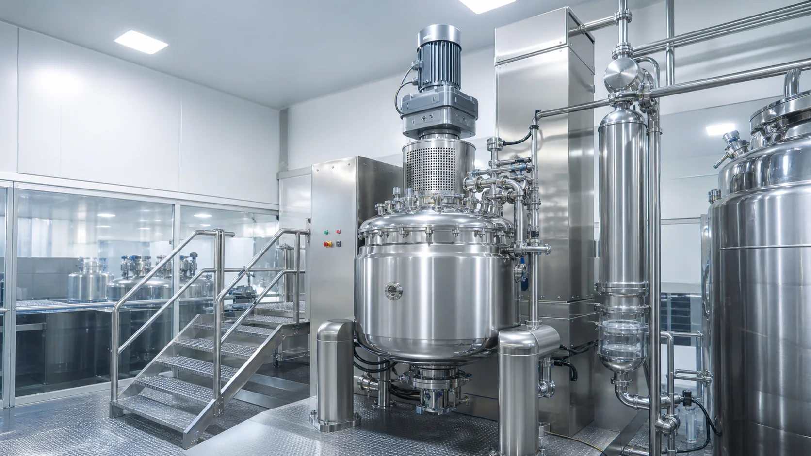
A vacuum emulsifying mixer should be configured from the process backward, not selected from tank capacity alone. Two vessels with the same nominal volume can perform very differently if their working range, homogenizer position, anchor geometry, vacuum duty, heat-transfer area, feed method or discharge path does not match the formula.
Quick answer: define the minimum and maximum batch, viscosity curve, powder and liquid addition sequence, required temperature profile, deaeration endpoint, cleaning method and downstream transfer pressure before fixing the machine. Then select the homogenizer, anchor and scraper, vacuum system, jacket and discharge arrangement as one operating system. A fast rotor-stator cannot compensate for poor bulk circulation or slow cooling.
Quick configuration matrix
| Process input | Configuration question | Typical design response | Evidence to request |
|---|---|---|---|
| Wide batch range | Will the homogenizer remain submerged and fed at minimum batch? | Check low-level operation, vessel geometry and recirculation path | Minimum-batch trial with temperature and visual turnover data |
| Viscosity rises during cooling | Can bulk product reach the shear zone and jacket wall? | Anchor with wall scrapers plus suitable homogenizer position | Mixing-time and temperature-uniformity results at final viscosity |
| Carbomers, gums or pigments | How are powders wetted without floating lumps? | Controlled subsurface draw-in, premix vessel or inline induction | Addition-rate test and screen for undispersed material |
| Air-sensitive appearance | What vacuum stage removes entrained air without product carryover? | Recipe-controlled vacuum, separator and foam allowance | Final density, bubble inspection and vacuum recovery record |
| Wax or fat phase | How fast must the batch heat, melt, emulsify and cool? | Sized jacket, utility controls and wall scraping | Heating/cooling curve using stated utility conditions |
| High-value product | How much remains in the vessel and transfer line? | Low-hold-up outlet, assisted discharge and recovery steps | Measured residual mass after a representative batch |
Start with product and batch inputs
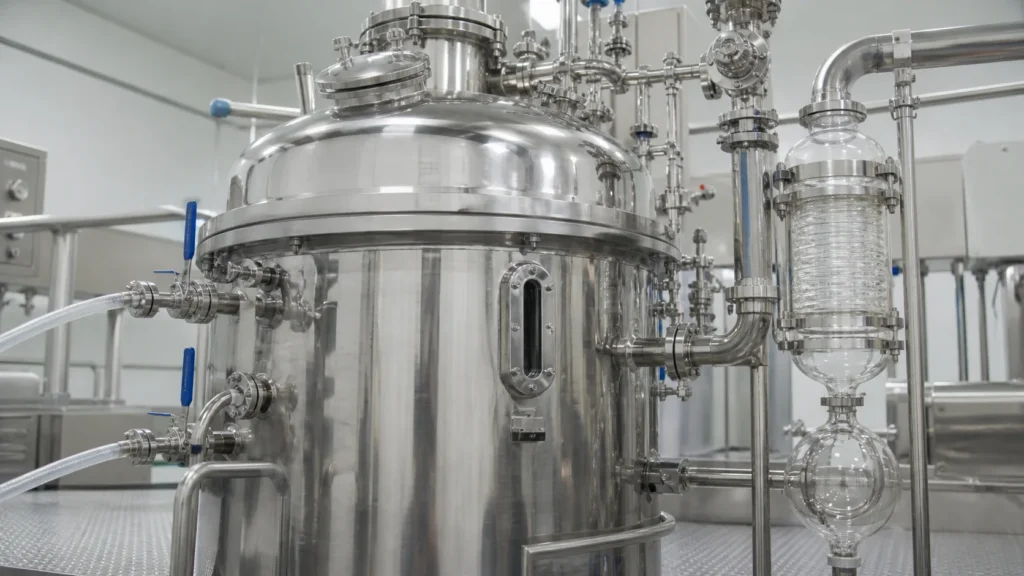
The useful specification begins with a batch envelope. State minimum, normal and maximum working mass or volume. Include density at charge and discharge, because a nominal 1,000-liter vessel does not automatically mean a 1,000-kilogram batch. Define acceptable headspace for foam, vacuum expansion and additions. If several formulas will run, identify the worst case for each machine function rather than naming one overall “worst product.”
Build a viscosity profile across the recipe. A lotion may be mobile during heating and become much thicker during cooling. An ointment may be difficult to circulate at the start while waxes melt, then change again after powders or active ingredients are added. The mixer must work through the complete curve. Give the supplier viscosity data with temperature and shear conditions, not a single number without a test method.
The formula sequence is equally important. List oil and water phases, powders, fragrances, heat-sensitive actives, colors and final corrections. Mark which additions occur under vacuum, which require a premix, which cannot tolerate high shear and which must be made below a temperature limit. This sequence determines ports, auxiliary pots, vacuum suction, dosing controls and sampling access.
Define quality endpoints in measurable terms. Examples include appearance, absence of visible agglomerates, density, viscosity at a stated method, temperature uniformity, droplet-size range, pH and residual air. The equipment supplier does not own the formulation acceptance criteria, but the configuration must make those criteria testable and repeatable.
Choose the homogenizer position and duty
The rotor-stator homogenizer creates localized high shear. Its job may include emulsification, powder deagglomeration, particle reduction or rapid wetting. First decide which duties are essential and when they occur. Continuous maximum shear is rarely the correct recipe for every phase; excessive exposure can heat the product, damage sensitive structures or waste energy after the endpoint is reached.
A top-entry homogenizer draws product through a head suspended in the vessel. Its working depth and head position can be adapted to the vessel, but the shaft, cover geometry and minimum submergence must suit the lowest batch. It can be attractive where access from the bottom is limited or where the process benefits from a defined head elevation.
A bottom-entry homogenizer places the shear zone near the vessel outlet and lowest liquid level. Official mixer literature commonly pairs this arrangement with a slow anchor or scraper for viscous products: the homogenizer treats material locally while the anchor feeds and redistributes the batch. Bottom entry can support low-level processing and short product paths, but seal access, outlet geometry and protection from settled solids must be reviewed.
For difficult powders or large batches, consider whether internal circulation is enough. Subsurface liquid or powder draw-in, an external recirculation loop or an inline high-shear stage can make turnover more measurable. The correct choice depends on addition rate, viscosity, shear sensitivity and cleanability. Do not add a loop merely to increase the equipment list; every valve and pipe adds hold-up and cleaning scope.
Use the existing vacuum emulsifying mixer types overview for a broad equipment map. This configuration guide focuses on converting process inputs into a project-specific mixer arrangement.
Match anchor and wall-scraper design to bulk circulation
High shear only works on product that reaches the homogenizer. The slow-speed agitator must move the bulk phase across the full vessel, exchange material between the top and bottom, and renew product at the heat-transfer wall. As viscosity rises, a simple central vortex is not proof of complete circulation.
Specify anchor geometry from the vessel diameter, bottom shape, baffles, ports and homogenizer location. Wall scrapers can reduce stationary films and improve heat transfer during heating or cooling. Their material, contact pressure, replacement method and compatibility with temperature and cleaning chemistry should be documented. Scrapers are wear items; include inspection criteria and spares in the project scope.
The agitator drive must cover the torque at the thickest verified condition, including starts after a planned hold. Ask how the drive is protected against overload and how recipe limits prevent operators from selecting an unsuitable speed. Variable speed is valuable when the process moves from low-viscosity charging to high-viscosity cooling, but the usable range must be demonstrated with the actual impeller and product behavior.
During trials, verify circulation rather than relying on motor current alone. Use temperature probes at more than one location, tracer addition, visual turnover where safe, or timed sampling. If the top layer, bottom zone or wall film responds slowly, adjust the anchor, scraper, fill level or homogenizer feed path before increasing shear indiscriminately.
Define vacuum duty and deaeration control
Vacuum can draw ingredients into a closed vessel, reduce surface aeration during mixing and remove entrained air near the end of the batch. Those are separate duties. The RFQ should state when vacuum is applied, the expected gas load, whether powders or liquids are inducted, the product foaming tendency and the required final quality indicator.
Avoid specifying only a deepest possible vacuum. A rapid pressure drop can expand foam, pull product into the separator or disturb a volatile ingredient. The recipe may need staged evacuation, controlled ramping and a hold at a validated endpoint. Provide a vacuum breaker or controlled venting method so the batch returns to pressure without splashing or re-aeration.
The protection train matters as much as the pump. Review condenser or separator capacity, product carryover detection, drainability and cleaning access. Identify what happens if foam reaches the separator and how the system recovers after a stop. The vacuum line should not become an unexamined product trap.
Use final density, a defined bubble check or another product-specific result to confirm deaeration. Vacuum time by itself is not a quality endpoint. For fragrances or other volatile ingredients, confirm addition temperature and vacuum timing during trials rather than assuming the same sequence as the base cream.
Size heating and cooling around the recipe
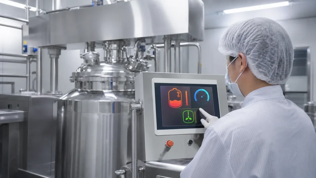
The thermal system should be specified with an energy balance and a required batch curve. List starting and target product temperatures, batch mass, heating and cooling times, phase changes such as wax melting, utility supply temperatures and allowable return conditions. Without these inputs, a jacket surface area or heater rating cannot be judged.
Mixing and heat transfer are coupled. Product must circulate across the jacket wall, and scrapers may be required to remove an insulating film. Official cosmetic processing references describe heating, controlled cooling and degassing as core operations for creams and ointments. They also emphasize that effective bulk circulation shortens thermal steps and improves temperature uniformity.
Choose steam, hot water, thermal fluid or electric heating from site utilities and control needs. Cooling may use plant water, chilled water or a staged combination. The most aggressive utility is not automatically best: wall temperature, formula sensitivity, condensation control and control-valve range can limit the practical approach.
Ask the supplier to state the assumptions behind the promised heating and cooling time. The test record should show batch size, product or simulant properties, initial and final temperature, utility supply and return temperatures, flow and agitation settings. Compare calculated performance with a witnessed trial where feasible.
Plan powder and liquid addition paths
Surface charging is simple, but it can create dust, floating rafts and fisheyes when a viscosity-building powder hydrates before it is dispersed. Controlled subsurface induction can wet powder into a moving liquid stream and reduce surface aeration. Official high-shear mixer references describe vacuum or inline induction as a way to wet powders quickly, but the system must be matched to powder behavior and feed rate.
For each powder, record bulk density, dustiness, tendency to bridge, hydration speed and maximum safe addition rate. Specify whether bags are opened at floor level, loaded into a hopper, transferred from a bulk system or premixed in an auxiliary vessel. Include operator ergonomics and dust control in the layout.
Liquid additions need similar detail. Large oil or water phases may come from dedicated premix pots; small actives may require a loss-in-weight or metered dosing approach. Define whether the addition must enter the rotor-stator shear gap, the bulk zone or a low-shear area. A fragrance added through the same high-shear path as a pigment may not be appropriate.
Challenge the addition sequence at minimum batch and maximum viscosity. Confirm that the suction remains stable, the feed does not block, and the operator can stop the addition without flooding a hopper or drawing air. Recipe control should record addition confirmation and prevent the next step when a critical feed is incomplete.
Engineer discharge, transfer and product recovery
The mixer is not finished when the recipe endpoint is reached. The product must move to a buffer tank, filling machine or mobile vessel without introducing air, changing temperature or leaving excessive residue. State transfer distance, elevation, pipe diameter, number of bends, receiving pressure and required flow.
High-viscosity creams may need positive displacement pumping, pressure-assisted discharge or a homogenizer that can support transfer. The best method depends on shear tolerance and cleanability. Confirm whether the discharge pump can run through the expected viscosity range and whether it requires a flooded inlet. Protect the system from deadheading and define how the last product is recovered without contaminating the next batch.
Measure yield during trials. Record charged mass, sample and filter losses, transferred mass and residual product in the vessel, outlet, pump and pipe. A low purchase price can be offset by recurring loss of a high-value formula. Design drain points and recovery steps into the operating procedure rather than treating residue as an operator problem.
Define cleaning, controls and scale-up evidence
Cleaning scope should follow product risk and changeover needs. Identify whether the machine will be manually cleaned, cleaned in place or use a hybrid approach. List every product-contact area, including seals, scraper supports, powder ports, vacuum separator, recirculation piping, sample valves and discharge components. Ask for spray-device coverage logic and a drainability review.
The control system should store recipe parameters that affect quality: agitator and homogenizer speeds, addition confirmations, temperature ramps, vacuum profile, time or endpoint logic and alarm responses. Define user roles, batch records, audit requirements and data export based on the site’s quality system. Avoid asking for software features that the factory cannot maintain, but do not leave critical settings as undocumented manual adjustments.
Scale-up should preserve the process mechanisms, not copy laboratory rpm. Compare rotor-stator geometry, tip-speed range, power input, turnover, batch depth, heating/cooling area and addition method. A production trial should include the minimum and maximum planned batch, the thickest formula stage and the most difficult powder. Record product quality by sample location and time.
For a broader explanation of process stages and equipment families, see what emulsifying equipment does. The production configuration still needs project-specific trials and acceptance criteria.
Configuration worksheet for an RFQ
| Input group | Required project data | Supplier response to demand |
|---|---|---|
| Product | Formula phases, viscosity vs temperature, density, shear sensitivity, foam and solids | Selected mixer duties and worst-case rationale |
| Batch | Minimum, normal and maximum working amount; headspace and campaign size | Usable working range and low-level limitations |
| Quality | Viscosity method, appearance, density, droplet or particle target, temperature uniformity | Test method, sampling plan and acceptance evidence |
| Thermal | Starting/target temperatures, allowed time, utilities and wall-temperature constraints | Jacket design, utility demand and stated performance basis |
| Additions | Powders, liquids, rates, sequence and vacuum restrictions | Port, premix or induction arrangement |
| Transfer | Receiving equipment, distance, elevation, viscosity and recovery target | Discharge method, pump duty and residual-volume estimate |
| Cleaning | Product change matrix, cleaning method, chemistry and verification | Coverage, drainability, seal and scraper cleaning plan |
| Controls | Recipes, users, records, alarms and interfaces | Functional description and FAT test cases |
Before approval, request a process flow, general arrangement, product-contact material list, utility list, instrument list, valve matrix, motor and seal data, cleaning concept, change-parts list and trial protocol. Each performance promise should include the product basis and test condition.
King Pack can translate these inputs into a mixer and downstream line concept. Start with the cosmetic filling and processing application page, then send the formula properties, minimum and maximum batch, temperature profile, powder-addition method and filling interface. The goal is a configuration that produces the required quality repeatedly, not the longest option list.
Frequently asked questions
What working volume should I specify for a vacuum emulsifying mixer?
Specify minimum, normal and maximum working amounts plus required headspace. Nominal vessel volume alone does not show whether the homogenizer, scraper and vacuum system will work at the lowest batch.
Is a bottom-entry homogenizer always better for thick cream?
No. It can support low-level processing and short circulation paths, but performance depends on vessel geometry, anchor feed, seal design and the formula. Compare it with a top-entry arrangement using representative trials.
How much vacuum is required?
The correct vacuum profile depends on deaeration endpoint, foam behavior, volatile ingredients and induction duty. Specify the result and recipe stages, then size the pump and separator from the gas load.
Do all creams need wall scrapers?
Not all. Scrapers are most valuable when wall films restrict heat transfer or product circulation. Their material, pressure, wear and cleaning method must be included in the design.
Can the homogenizer discharge the finished product?
Some systems can assist internal or external transfer, but verify flow, pressure, shear exposure, residual volume and cleanability at final viscosity before using it as the discharge solution.
How should heating and cooling performance be compared?
Compare a full batch curve with stated product properties, batch size, utility temperatures, flow and mixing settings. A time claim without those conditions is not comparable.
What should be tested before purchase?
Test minimum and maximum batch, the thickest stage, the most difficult powder addition, vacuum deaeration, thermal curve, discharge yield, cleaning access and recipe recovery after a stop.