
Tube Filling Line Layout and Utilities: A Practical Planning Guide
Planning a tube filling line layout is a coordination exercise between production, engineering, maintenance, quality and facilities. The machine footprint is only one part of the decision. Operators need access, product and tube materials need a controlled route, utilities need practical connection points, and downstream coding, inspection or cartoning must fit the actual workflow.
This guide helps project teams prepare a layout and utilities brief before ordering a tube filling machine. It uses a site-planning approach for pharmaceutical, cosmetic, personal-care, food and industrial products. Exact utility values and connection details must be confirmed against the selected configuration, local standards and the supplier’s final drawings.

Start with process flow, not the machine outline
Draw the process from incoming tubes and bulk product to filled, sealed, coded and discharged tubes. Mark where operators load materials, where product is transferred, where inspections occur and where finished tubes move to the next packaging step. This exposes crossovers, long manual carrying routes and access conflicts before the equipment arrives.
Separate the normal production route from maintenance and cleaning routes. A machine may run in one direction while technicians need to open guards, remove product-contact parts or access electrical and pneumatic components from another side. Include those activities in the early drawing rather than treating them as an installation detail.
| Layout question | Why it matters | Information to confirm |
|---|---|---|
| Material flow | Reduces handling and prevents avoidable crossovers | Tube storage, product route, finished-goods handoff |
| Operator access | Supports loading, inspection and safe response to alarms | Working zones, control-panel position and line-of-sight |
| Maintenance access | Allows removal of parts and service work | Guard opening, lifting and clearance requirements |
| Cleaning route | Protects hygiene and controls product residue | Part removal, wash area, waste route and restart checks |
| Downstream interface | Prevents accumulation or starvation at cartoning and inspection | Conveyor height, speed relationship and reject handling |
Reserve practical access zones
Use the supplier’s general arrangement drawing as the starting point, then add site-specific access zones. Keep the control panel visible from the operating position where possible. Leave room for operators to load tubes, observe the filling and sealing stations, check codes and remove finished products without reaching across moving equipment.
Maintenance access should account for the largest part that may be removed, not only the normal gap between machines. If a hopper, pump, nozzle plate, sealing tool or conveyor section needs to be lifted or slid out, identify the path and lifting method. Confirm whether the machine can be moved for service or whether the room must provide permanent rear and side access.
Consider future change parts and SKU growth. A line that fits one tube size can become difficult to operate when additional holders, guides, nozzles or sealing tools need to be stored and prepared. Assign a clean, labeled place for format parts near the changeover area.
Plan product and tube material movement
Product transfer may involve a bulk vessel, hose, pump, hopper or another upstream system. The route should minimize unnecessary bends and avoid placing connections where operators or forklifts can damage them. Discuss how the line is isolated, drained or cleaned before deciding the final path.
Tubes need a controlled presentation to the loading station. Plan storage, unpacking, orientation and replenishment so cartons or bins do not block access. If the tube filler connects to an automatic tube feeder, check the interface height, tube direction, sensor responsibilities and the space needed for replenishment.
Utilities: confirm, document and verify
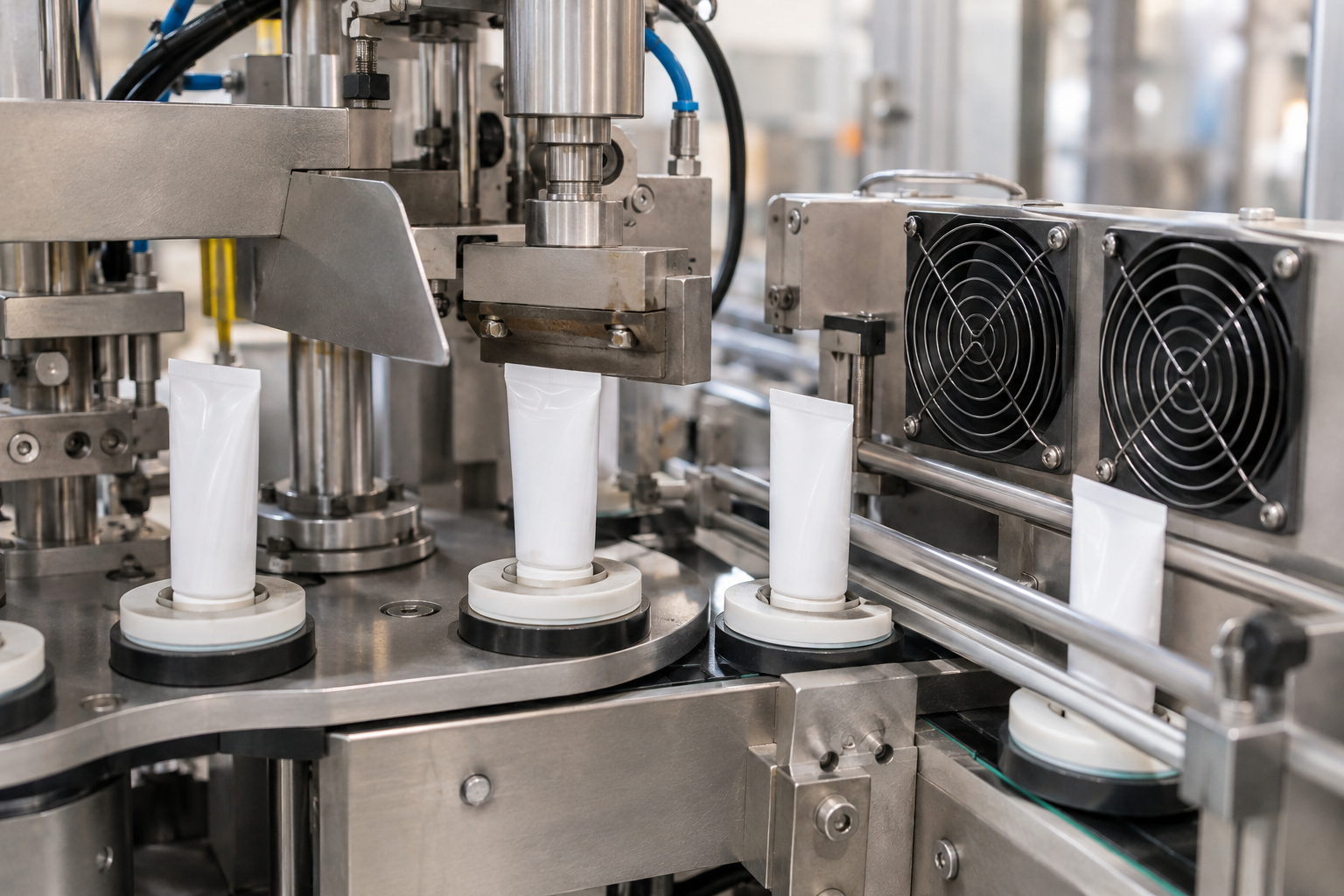
Utilities are configuration-specific. Request a final utility sheet that identifies compressed air quality and pressure range, electrical supply, connected load, exhaust or ventilation needs, cooling or heating requirements where applicable, and any product or cleaning connections. Do not use a generic number from another machine as the installation basis.
Compressed air planning should include the source, filtration, regulator, isolation valve, drain arrangement and the route to the machine. Confirm whether the machine needs dry and clean air for product-contact or pneumatic components. The site team should verify that the available supply remains stable when other equipment starts.
Electrical planning should address voltage, frequency, phase, disconnect location, cable route and grounding. Confirm whether control cabinets require a temperature-controlled environment and whether network access is needed for diagnostics or data collection. Local electrical codes and the supplier’s drawings govern the final installation.
Ventilation and heat considerations depend on the product and sealing method. If hot-air tail sealing, coding or other equipment creates heat or fumes, ask the supplier to describe the expected extraction or room conditions. Materials and process steps should be matched to the actual tube and closure design.
Coordinate downstream cartoning and inspection
A tube filling machine rarely operates in isolation. Downstream equipment may include checkweighing, vision inspection, metal detection, labeling, cartoning or case packing. Define the finished-tube orientation, conveyor height, discharge rate relationship, reject path and accumulation strategy.
When cartoning is planned, use the tube filling and cartoning line overview to frame the interface discussion. Ask where the handoff occurs, which controls belong to each machine, how a downstream stop affects the filler and how products are recovered after a line restart.
Inspection should be reachable and meaningful. If operators must remove a sample, the sample point should be safe and clearly labeled. If rejects are automatically diverted, reserve a container and access route that do not interfere with normal material flow.
Include cleaning, changeover and waste paths
Cleaning requirements should influence the layout from the beginning. Identify where product-contact parts are removed, where they are carried, how spills are contained and where waste or wash materials go. A narrow route or a shared aisle can make a routine changeover slow and unsafe.
For multiple tube formats, provide a changeover staging area. The team should be able to verify the correct guides, holders, nozzles, sensors and sealing tools before the machine is opened. Review the cleaning and changeover checklist and map its activities to physical locations.
Drain or recovery routes depend on the formulation and the site’s hygiene procedure. Confirm whether product is recovered, discarded or transferred for cleaning. Keep the waste path away from incoming tube storage and finished-product movement where practical.
Prepare an installation package
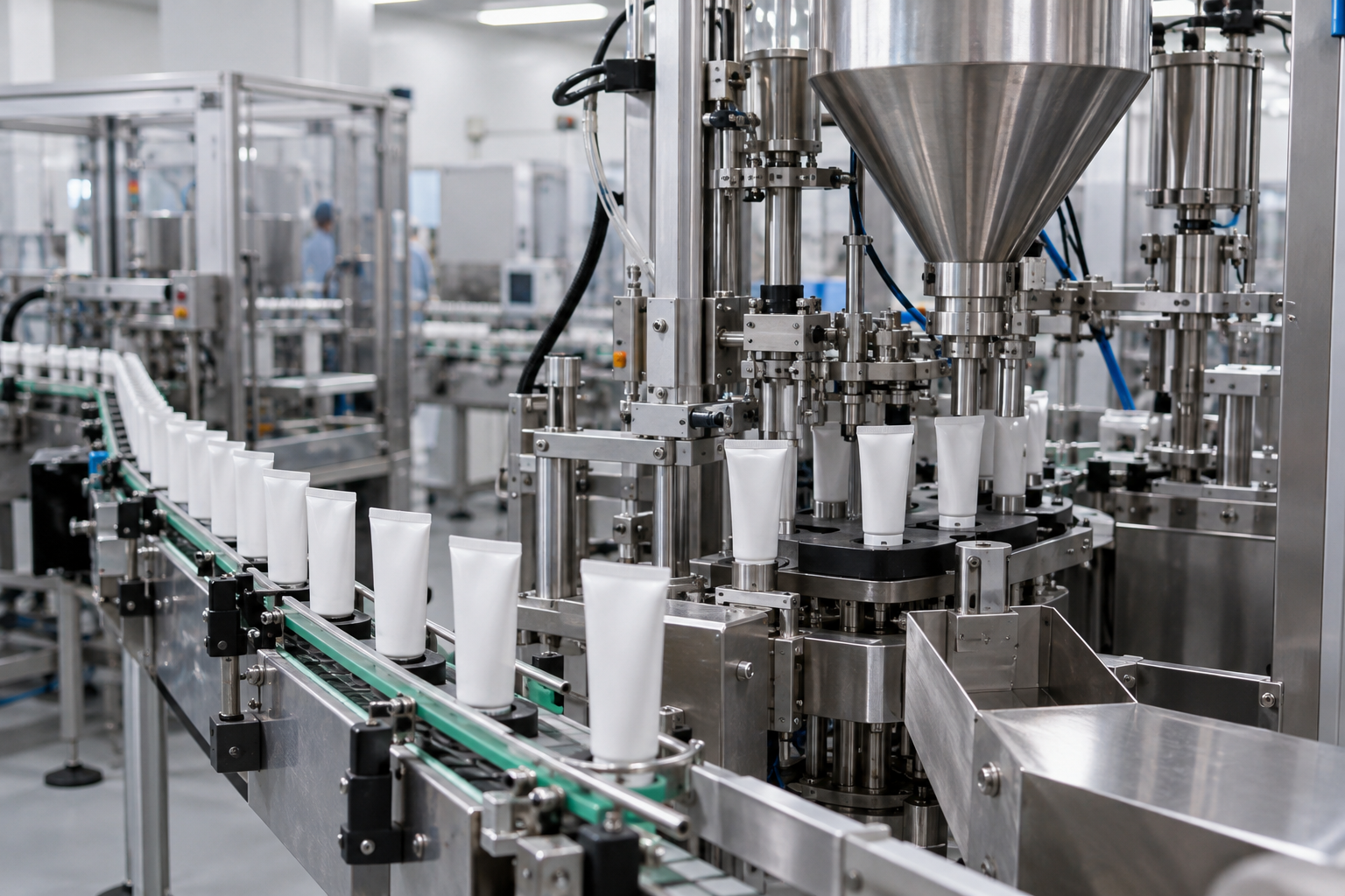
Before shipment, collect the approved general arrangement drawing, foundation or floor information if applicable, utility sheet, electrical drawings, connection list, lifting and access requirements, recommended spare list and installation sequence. Share the package with production, maintenance, quality, facilities and the contractor responsible for moving the equipment.
Confirm the route from unloading point to final position. Check door widths, ceiling height, turns, floor loading, temporary removal of barriers and the location of staging space. Include a method for protecting the machine and product-contact parts while other construction or installation work continues.
During installation, use a punch list that separates mechanical setup, utilities, controls, safety, cleaning, sample trials and operator training. The machine should not be considered ready because it is powered on; the site needs evidence that the agreed sequence and handover requirements are complete.
Questions to ask before approving the layout
- Can operators load materials, inspect tubes and respond to alarms without crossing moving equipment?
- Can the largest removable part be taken out safely for cleaning or service?
- Are product, tube, finished-goods and waste routes clearly separated?
- Does the utility sheet match the exact proposed configuration?
- How will a downstream cartoner stop affect the filler and accumulation area?
- Where will change parts be identified, staged and stored?
- What must be ready before installation, FAT follow-up and commissioning?
Use a layout review with every affected team
A layout drawing should be reviewed by more than the equipment buyer. Production can confirm material flow and operator tasks; maintenance can confirm service access and lifting; quality can review sample and reject paths; facilities can confirm utilities; and the downstream packaging team can check conveyor and accumulation interfaces. Each review should produce a marked-up action list.
Walk the proposed route from unloading to final position. Check doors, turns, temporary staging, floor conditions and the path for the largest removable component. Confirm where tubes, bulk product, finished goods, waste and change parts will wait during a normal shift. These details often have more effect on daily usability than a small difference in the machine footprint.
Keep utility assumptions separate from confirmed data. Early planning can reserve a service zone, but the final installation should use the selected machine’s utility sheet, approved drawings and local code requirements. If another machine shares compressed air or electrical capacity, verify the effect of simultaneous operation.
Reviewing a new line layout? Send the room drawing, product route and downstream equipment details for a layout discussion.
Plan for commissioning and future change
Installation preparation should include a responsibility matrix. Identify who provides the foundations or floor preparation, utility connections, lifting equipment, product and tube samples, safety review, cleaning materials and operator training. This prevents the machine from arriving before the site is ready to complete the agreed checks.
Reserve space for future format parts, inspection equipment or cartoning interfaces only when the project has a clear reason to do so. Mark those provisions on the drawing so they are not mistaken for equipment included in the current order. A future interface should have a defined boundary, access requirement and control responsibility.
After commissioning, update the as-built layout and utility record. Record any moved panel, revised hose route, added guard or changed conveyor position. The final drawing should represent how the line is actually operated and maintained.
Make utilities part of the acceptance package
At installation, compare the actual connections with the approved utility sheet. Check isolation valves, regulators, filters, cable routes, grounding, exhaust or ventilation provisions and access to the control cabinet. Record any deviation on the commissioning punch list and update the as-built record after it is resolved.
Ask the supplier to identify the conditions that can affect process stability. A changing air supply, an unsuitable product transfer route or an unplanned temperature condition can create a production issue that appears to be a filling-machine fault. The layout review should therefore connect the machine interface with the site’s utilities and upstream process.
Provide a clear handover to the operators and maintenance team. Mark the normal material route, sampling point, reject location, cleaning path and service clearances on the final drawing. These details help the team use the layout as an operating reference instead of leaving it as a construction document.
Keep the approved layout current
Store the final layout with the utility sheet, equipment list and installation records. If a conveyor, control cabinet, hose or service panel moves during commissioning, update the drawing rather than relying on a verbal handover.
Use the layout during operator training and maintenance planning. Mark sample points, emergency access, cleaning routes and change-part staging so the drawing supports the work that happens around the machine.
A current layout also helps future projects assess whether another filler, inspection step or cartoner can be integrated without blocking existing service and material routes.
FAQ
How much space does a tube filling line need?
There is no universal room size. Use the supplier’s final footprint, add operating and service access, and include material staging, cleaning, change parts and downstream equipment.
Can utilities be finalized from a catalogue?
Use catalogue information only for early planning. Final air, electrical, exhaust and connection requirements must come from the selected machine configuration and approved drawings.
Should cartoning be planned at the same time?
Yes when it is part of the project. Define conveyor height, tube orientation, speed relationship, reject handling and control signals before the filler layout is frozen.
What causes layout problems after installation?
Common causes include missing service clearance, an overlooked material route, utilities placed on the wrong side, inadequate change-part storage and an unplanned downstream accumulation area.
Conclusion
A workable tube filling line layout connects process flow, access, product and tube movement, utilities, cleaning and downstream packaging. Start with the actual workflow, confirm configuration-specific utility data, and validate the installation route before shipment. A clear layout package gives every project team the same reference for installation, commissioning and future changeovers.
Planning a new line? Send Your Requirements with the product, tube drawings, room constraints and downstream equipment details. King Pack can review the proposed scope and identify the information needed for the next layout discussion.