 Skip to content
Last reviewed: September 15, 2026.
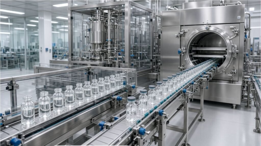
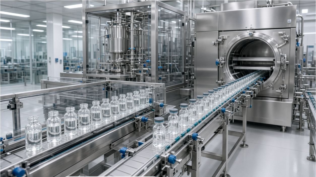
Liquid and lyophilized veterinary vaccines can share vial preparation, accurate filling and final closure operations, but their line boundaries diverge after dosing. A liquid presentation normally proceeds from filling to full stoppering and capping within the defined aseptic process. A lyophilized presentation normally needs controlled partial stoppering, protected transfer into a freeze dryer, drying and chamber stoppering, followed by return transfer and capping. The final design depends on the approved product process, container-closure system, facility concept and market requirements.
This article compares only the equipment and facility interfaces created by those two dosage-form paths. It does not prescribe a vaccine formulation, freeze-drying recipe, sterilization cycle or regulatory strategy. The existing KING PACK vial filling and processing overview remains the broad parent page; this page owns the liquid-versus-lyophilized transfer and stoppering decision.
Quick answer: Choose the line architecture from the approved post-fill process. A liquid vaccine generally needs filling, full stoppering, capping and inspection in a defined sequence. A lyophilized vaccine adds partial stoppering, an aseptic transfer boundary to and from the freeze dryer, chamber-compatible loading, full stoppering in or after the dryer as designed, and return to capping. Confirm vial and stopper drawings, dose range, product exposure limits, dryer loading pattern, transfer method, room and barrier concept, intervention strategy and acceptance tests with representative components before finalizing equipment.
1 Set the Dosage-Form Decision Before Selecting Equipment
Direct answer: The first decision is whether the commercial presentation leaves the filler as a liquid or enters a qualified lyophilization process before final closure.
Document the product state at filling, nominal and allowable dose range, vial and stopper system, required headspace or gas handling, allowable time between filling and closure, temperature constraints and the intended final closure sequence. These are product and process inputs, not machine defaults. If either presentation may be produced, describe both routes and their forecast volumes rather than asking for one undefined flexible line.
Define the regulatory and quality basis with the manufacturer’s specialists. FDA’s aseptic-processing guidance and EU GMP Annex 1 provide relevant sterile-manufacturing context, but they do not select a freeze dryer, stopper position or transfer method for a specific veterinary vaccine. The owner must establish applicable requirements and approved acceptance criteria.
Separate fixed facts from values still under development. The concept design can reserve interfaces, space and controls for an uncertain future route, but an unresolved formulation or closure study should remain an open project risk. Do not convert a supplier assumption into a product requirement without documented approval.
| Required input | Liquid presentation | Lyophilized presentation |
|---|---|---|
| Post-fill route | Full stopper and cap | Partial stopper, dryer transfer, full stopper, cap |
| Main line boundary | Filler to closure and inspection | Filler, transfer system, dryer and return |
| Critical component data | Vial, stopper and cap | Vial, lyo stopper, cap and dryer shelf pattern |
| Evidence focus | Dose, full seating and closure | Dose, partial position, transfer and final seating |
Direct answer: Both routes need controlled component specifications, preparation status and handling boundaries before a common filling platform can be evaluated.
Provide dimensioned drawings and representative lots for vial outside diameter, height, neck and finish, base geometry, stopper dimensions, flange or lyophilization features and cap. Identify material, supplier, sterilization or depyrogenation status, packaging presentation and allowed handling. Nominal dimensions alone are insufficient for guide, starwheel, nest, stopper-track and sensor design.
Map component flow from receipt through preparation and presentation to the filling zone. State whether vials arrive ready to use or require washing and depyrogenation, and whether stoppers require washing, sterilization and protected transfer. Each project must set its own contamination-control and hold-time strategy; the equipment proposal should show where responsibility changes between modules and rooms.
Use sample testing to confirm conveying, centering, stopper pickup, partial and full seating, cap fit and inspection visibility. A component that functions manually may behave differently at production speed or after real preparation. Keep lot identity and tolerance conditions in the test record so results can support design decisions.
3 Configure Liquid-Vaccine Filling and Full Stoppering
Direct answer: For a liquid presentation, the core downstream objective is to fill within the approved process window and establish the specified final stopper position before capping.
Select the dosing principle from dose range, product behavior, product-contact requirements, allowable residual, cleaning or single-use strategy and required control evidence. The KING PACK pump-selection comparison can frame that decision, but representative product studies must establish suitability for the vaccine and container.
Define nozzle entry, fill motion, stoppering timing and any headspace or gas-handling steps from approved process knowledge. Challenge startup, normal running, planned stop, restart, low feed condition and batch end. Record dose results, splashing, stopper-zone cleanliness, interventions and segregated units rather than relying on a steady-state demonstration.
Full stoppering equipment should handle the specified component without damage, incomplete seating or uncontrolled intervention. Establish the approved evidence: seating position, visual criteria, force or functional checks and container-closure integrity studies as applicable. FAT can challenge machine functions; the manufacturer remains responsible for product-specific closure qualification and release.
4 Configure Lyophilized-Vaccine Filling and Partial Stoppering
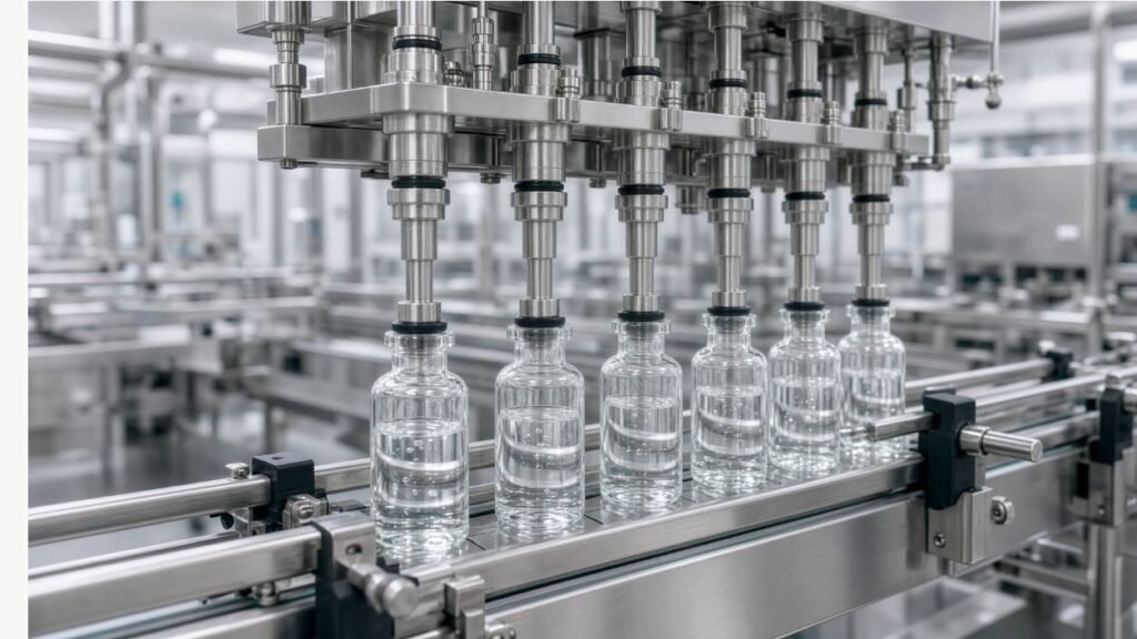
Direct answer: A lyophilized presentation requires a repeatable partial-stopper position that supports vapor flow, protected transfer and the defined chamber-stoppering process.
Provide the lyophilization stopper drawing, validated or proposed partial position, allowable force and visual or dimensional acceptance method. The track, pickup tooling and insertion motion must handle the prepared stopper without touching critical surfaces. Test component tolerance and surface condition after the intended preparation process, not only dry engineering samples.
Define how the machine detects missing, inverted, doubled or incorrectly positioned stoppers and what happens to affected vials. Partial seating can be harder to distinguish from a marginal position than full seating, so detection limits and offline sampling should be linked to a documented defect list. Do not promise complete detection until trials establish the actual contrast and tolerances.
Control splashing and closure-zone contamination before partial stoppering. Coordinate dose cutoff, vial motion and stopper placement, then challenge planned stops and restarts. The approved operating procedure should address exposed filled vials, jam recovery and line clearance without creating undocumented manual handling.
| Stoppering risk | Engineering challenge | Evidence |
|---|---|---|
| Wrong partial position | Tolerance samples and force window | Measured position and trend |
| Missing or inverted stopper | Defined fault samples | Detection and reject or stop response |
| Closure-zone contamination | Startup and restart challenge | Visual or approved cleanliness result |
| Component damage | Prepared stopper lots | Inspection and functional result |
5 Engineer Transfer to the Freeze Dryer
Direct answer: The filler-to-dryer transfer must preserve the defined aseptic state, vial spacing and partial-stopper position while meeting dryer loading constraints.
Specify the transfer concept: manual carts under a qualified barrier, automated guided transport, conveyor, loading robot or another site-approved method. Record maximum route length, elevation, turns, accumulation, batch pattern and allowed transfer time. The freeze-dryer supplier, filling-line supplier and facility designer must agree on physical, control and responsibility boundaries.
Provide shelf dimensions, usable loading area, vial pitch, row and batch pattern, loading height and any frame or tray geometry. Model the required number of vials from actual package dimensions and qualified loading rules rather than using nominal shelf area alone. Confirm that acceleration, gaps and contact surfaces do not tip vials or disturb stoppers.
Review barrier continuity, door sequencing, environmental classification, decontamination interfaces and intervention points with the site’s contamination-control strategy. EU GMP Annex 1 emphasizes a risk-based contamination-control approach; it does not provide a universal transfer layout. The project team must justify the chosen system and its monitoring.
6 Coordinate Chamber Stoppering and Return Transfer
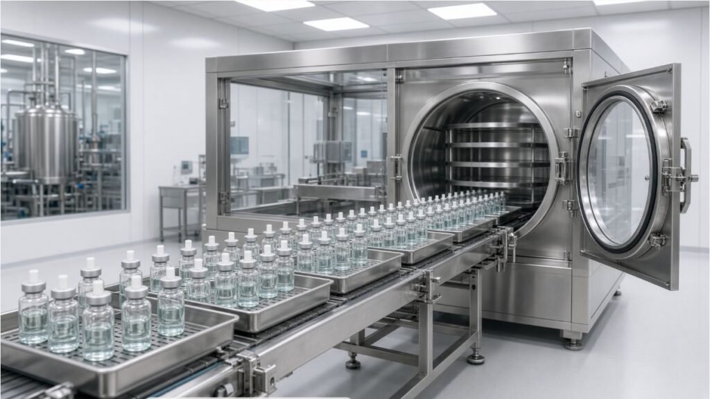
Direct answer: The dryer, stopper geometry and return system must be treated as one interface from chamber loading through capped-vial handoff.
Clarify whether full stoppering occurs inside the freeze dryer by shelf compression or through another approved sequence. Define stopper compression, vial support, shelf movement and release conditions with the dryer and component suppliers. Filling-line documentation should reference the agreed state of the vial entering and leaving the dryer.
After drying and stoppering, map unloading, protected transport, accumulation and handoff to the capper. State allowed time and environmental conditions before capping, and determine how stalled or exposed batches are managed. Avoid an uncontrolled buffer that separates a qualified chamber process from closure completion.
Exchange batch identity, readiness, door status, permissives, alarms and completion signals across control systems. Define who owns each signal and safe state. Simulate loss of communication, unavailable downstream equipment and an interrupted unload during FAT or an integrated test where feasible.
7 Compare Facility, Barrier and Utility Consequences
Direct answer: Lyophilized production normally creates more facility and automation interfaces than a liquid-only route, even when the filler and capper are shared.
Compare room layout, barrier technology, personnel and material routes, maintenance access, cleaning zones, transfer path, freeze-dryer location and return flow. Check whether the selected concept permits safe access without crossing component or product paths. Facility decisions should be resolved early because they influence equipment orientation and validation scope.
List utilities for each module, including electrical power, compressed gases, vacuum, cooling, steam or water where applicable and environmental exhaust. Confirm quality, pressure, temperature, capacity, redundancy and connection points with the actual supplier loads. Do not publish generic utility values as project requirements.
For a combined liquid and lyophilized line, define route selection, recipes, physical change parts, cleaning or sterilization boundaries and line-clearance checks. Flexible architecture adds control and validation work; it is justified only when forecast, campaign and facility benefits exceed that burden.
8 Plan Capping, Inspection and Batch Reconciliation
Direct answer: Both product routes converge only when the incoming vial state, cap application and inspection responsibilities are explicitly defined.
Provide cap drawings, feeding presentation, closure sequence, force or crimp requirements and approved acceptance tests. Verify the capper receives a fully seated stopper. If the same capper serves both routes, challenge transfer timing, product recipes and components from both presentations rather than assuming identical behavior.
Create a defect list that includes fill result, vial damage, stopper position, missing closure, cap appearance, coding and route-specific conditions. Allocate automatic inspection and offline sampling, and state detection limitations. Inspection equipment cannot compensate for an unstable fill or transfer process.
Reconcile vials across filling, dryer loading, unloading, rejects, samples and capped output. Define batch and recipe identity across connected systems. The KING PACK filling and capping line platform is a starting point for interface review; final data and reporting scope must be project specific.
9 Convert Interface Risks into FAT Tests
Direct answer: A useful FAT challenges line states and handoffs, not only continuous operation with ideal components.
Prepare a risk-to-test matrix covering vial infeed, dose, partial or full stoppering, missing and misoriented closures, transfer readiness, dryer communication, loss of permissive, downstream stop, cap application, inspection and reject reconciliation. State the component lots, product or surrogate, sample sizes and approved methods before execution.
For the liquid route, include startup, steady operation, stop, restart, full stoppering and capping. For the lyophilized route, include partial-stopper position, transfer pattern, simulated dryer loading and unloading, control handshakes and return to the capper. Document any simulation limits honestly.
Record settings, raw results, alarms, interventions, deviations and unresolved actions. FDA process-validation guidance supports lifecycle evidence from design through qualification and continued verification; FAT contributes equipment evidence but does not replace site qualification, process performance qualification or product studies.
| Interface | FAT challenge | Acceptance evidence |
|---|---|---|
| Liquid route | Start, stop, restart, full stopper and cap | Dose and closure records |
| Lyo route | Partial stopper and transfer pattern | Position, stability and count |
| Dryer handshake | Ready, fault and communication loss | Permissive, alarm and safe-state response |
| Batch tracking | Rejects, samples and route change | Reconciliation and identity record |
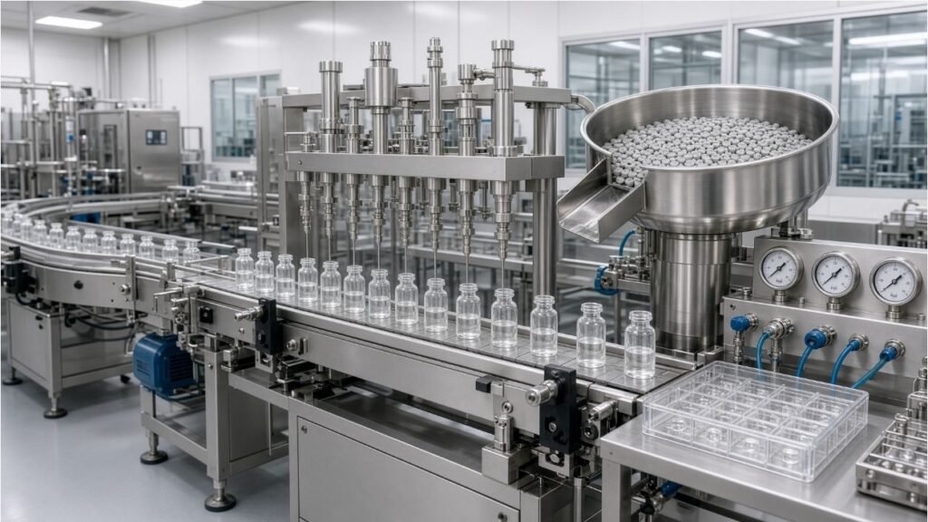
10 Use a Supplier Interface Responsibility Matrix
Direct answer: The project should assign every mechanical, utility, control, documentation and validation interface to a named owner.
List the vial preparation equipment, filler, stopper system, barrier, transfer system, freeze dryer, unloader, capper, inspection, serialization or coding, facility controls and data systems. For each boundary, record supply scope, installation, testing, signal definition, document owner and acceptance evidence.
Request layout, line diagram, product path, component path, interface-control document, I/O list, alarm matrix, recipe and access concept, material certificates as scoped, spare and change-part list, manuals and proposed FAT protocol. Cross-check revision numbers so the dryer loading pattern and filler discharge height do not diverge during design.
Use design reviews to close assumptions before fabrication. An interface marked 'by others' still needs dimensions, timing, signals and evidence. The owner or integrator should maintain the master boundary document and track changes through the project quality system.
11 Review the Veterinary Vaccine Vial Line with KING PACK
Direct answer: KING PACK can translate approved dosage-form and container inputs into a preliminary liquid or lyophilized vial-line boundary and sample-test plan.
KING PACK Machinery is a China-based manufacturer of pharmaceutical, veterinary, cosmetic and liquid filling and packaging equipment, with core solutions covering vial and liquid filling, capping, tube filling and sealing, vacuum emulsifying, pet spot-on filling and syringe production systems.
For this project, the review can cover vial infeed, dosing, full or partial stoppering, barrier and transfer interfaces, dryer handshakes, return transport, capping, inspection, rejects, recipes, utilities, documentation and FAT. The manufacturer and its quality team retain responsibility for the vaccine process, contamination-control strategy, closure qualification and release criteria.
Send dosage form, dose range, batch and output targets, vial and closure drawings and samples, preparation status, product exposure limits, freeze-dryer supplier and shelf pattern, room and barrier concept, utilities and approved tests through the KING PACK contact page. These inputs support a focused line-boundary review rather than a generic quotation.
Frequently Asked Questions
What is the main line difference between liquid and lyophilized veterinary vaccines?
A liquid route normally proceeds to full stoppering and capping. A lyophilized route adds partial stoppering, protected dryer transfer, drying, chamber or approved final stoppering, return transfer and capping.
Can both products use the same vial filler?
Potentially, if dose, product-contact, vial, stopper, barrier, cleaning and control requirements are compatible. Confirm both routes with documented design review and representative trials.
Why is partial stoppering a separate equipment risk?
The position must support vapor flow and remain stable during transfer while protecting critical closure surfaces. Component tolerances and detection limits must be tested.
Who defines the freeze-dryer loading pattern?
The product owner, dryer supplier, filling-line supplier and facility team should agree on shelf geometry, vial pitch, batch pattern, transfer method and responsibility boundaries.
Does FAT prove aseptic suitability?
FAT can challenge equipment functions, interfaces and records. Site qualification, contamination-control evidence, process simulations and product validation remain separate responsibilities.
What should an integrated control test include?
Test readiness signals, permissives, door or barrier states, transfer completion, downstream unavailable conditions, communication loss, alarms and defined safe states.
How is this page different from a general vial-filling guide?
It owns liquid-versus-lyophilized post-fill architecture, partial stoppering and freeze-dryer interfaces; broad vial-machine selection remains on existing pages.
What should be sent to KING PACK?
Send the dosage form, dose range, vial and stopper drawings and samples, dryer shelf pattern, transfer concept, facility constraints, utilities and approved acceptance tests.
