
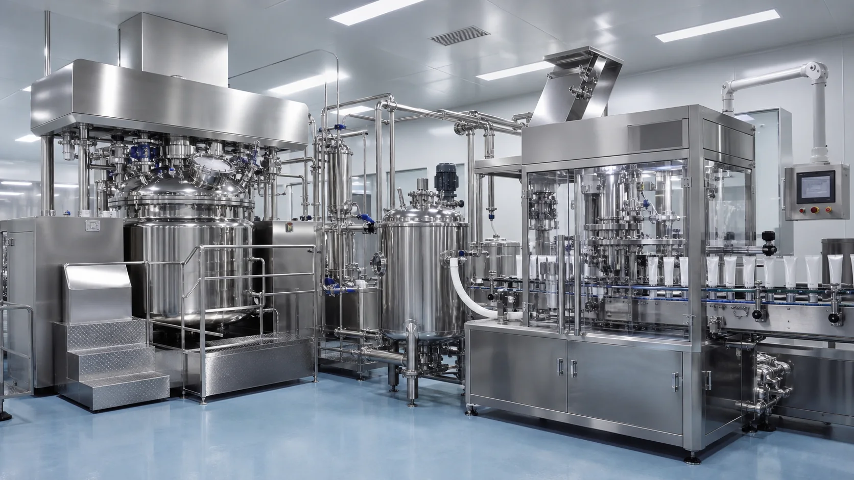
Pharmaceutical Ointment Manufacturing Line: Vacuum Emulsifying, Transfer and Tube Filling
A bulk-to-tube process guide for rheology, deaeration, cooling, hygienic transfer and validated filler feed
Quick answer
A pharmaceutical ointment manufacturing line should be engineered as one controlled process from phase preparation to the sealed tube. The key design task is to preserve the product’s approved rheology and microbiological control while moving it through vacuum emulsification, homogenization, deaeration, cooling, holding, transfer and filling. Equipment capacity alone is not enough: the URS must define batch size, critical temperatures, shear history, vacuum endpoint, hold time, transfer pressure, filler-feed conditions, cleaning boundaries and the evidence required for qualification and process validation.
The most common project gap is an undefined interface between the manufacturing vessel and tube filler. When product temperature, viscosity, pressure, air content or hopper level changes at that interface, the filler may show dose drift, stringing, bubbles or unstable cutoff even though both machines run correctly in isolation.
Related KING PACK resources: pharmaceutical industry solutions; vacuum emulsifying mixer types and applications; cream tube filling machine guide; basic ointment filling-machine explainer; contact and project consultation.
1. Quick process map: control the interfaces
| Stage | Primary engineering decision | Evidence to define or collect |
|---|---|---|
| Phase preparation | Addition order, temperature and premix capability | Formula process description, vessel load and temperature record |
| Emulsifying/homogenizing | Shear device, speed profile and circulation path | Development data, endpoint attributes and scale-up rationale |
| Vacuum deaeration | Vacuum level, product temperature and endpoint | Air-content or appearance criteria; trend record |
| Cooling/holding | Cooling rate, agitation and maximum hold time | Temperature/rheology trend and microbial-control rationale |
| Transfer | Pump type, line diameter, pressure and drainability | Pressure envelope, residual volume and recovery study |
| Filler feed | Hopper level, temperature and pressure consistency | First-off/steady-state dose and cutoff evidence |
| Tube filling/sealing | Dose, tail cleanliness and material-specific closure | Fill-weight data, seal challenges, reject records |
FDA process-validation guidance applies to human and animal drugs and describes a lifecycle linking process design, qualification and continued process verification. For the equipment project, that means defining the scientific basis for each critical interface before FAT rather than trying to create the process after installation.
2. Define product and batch before choosing equipment
Start with the intended product profile and approved formulation process. Ointment is not a single viscosity class. Petrolatum-rich bases, emulsified creams, water-miscible gels and particle-containing products can respond differently to temperature, shear, vacuum and pumping. Record viscosity or rheology with the method, spindle or geometry, shear condition and temperature; a value without its measurement condition is not a useful design input.
- Minimum, normal and maximum batch size, including usable vessel working volume.
- Phase ratio, addition order, solid or powder incorporation and premix needs.
- Temperature limits for heating, emulsification, active addition, cooling and filling.
- Shear sensitivity, yield behavior, thixotropy, density, air-entrainment tendency and particles.
- Maximum bulk hold time, microbial-control assumptions and required environmental controls.
- Target tube sizes, fill weights, output, tube material and seal or fold method.
3. Phase preparation determines repeatability
Oil and water phases should reach the defined state before combination. Vessel geometry, heating surface, agitation and addition route affect dissolution, wetting and heat-up time. A line concept should show where solids are charged, how lumps are prevented, how operators avoid uncontrolled air draw-in and how phase transfer is confirmed. For potent or sensitizing actives, containment and cleaning requirements may dominate the layout.
Scale-up should preserve the process mechanism, not blindly copy laboratory rpm. Tip speed, energy input, circulation pattern, batch height and heat-transfer area change with scale. The development team should identify the attributes used to establish the endpoint, such as appearance, particle or droplet distribution, viscosity profile, assay uniformity or another approved test.
4. Vacuum emulsifying and homogenizing
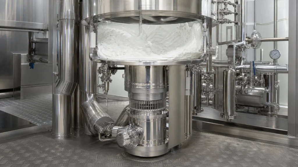
A vacuum emulsifying system combines controlled agitation, high-shear processing, heating/cooling and vacuum in a closed vessel. The appropriate arrangement depends on formula behavior and batch range. Homogenizer position, recirculation path and rotor-stator selection should be evaluated with representative product rather than chosen from a catalogue speed alone.
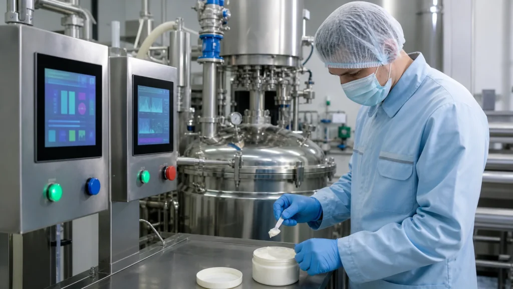
The process recipe should define addition sequence, agitation range, homogenization steps, vacuum application and endpoint conditions. Critical values need controlled access and version identification where electronic recipes are used. Excess shear can alter structure or introduce heat, while insufficient circulation can leave nonuniform zones. Sampling points and methods must represent the batch without creating contamination or untracked loss.
5. Deaeration and cooling are coupled
Vacuum can remove entrained air, but the effective endpoint depends on viscosity, temperature, headspace, agitation and surface renewal. Pulling vacuum too aggressively can cause foaming or volatile loss; applying it after the product becomes too viscous can make air removal slow. The URS should specify controllable vacuum and product-temperature ranges plus a justified endpoint rather than a fixed universal value.
Cooling changes viscosity and therefore mixing load, transfer pressure and filler behavior. Define cooling rate, final transfer temperature and agitation strategy. Continue mixing only as needed to maintain uniformity without drawing air or damaging structure. Record motor load or torque trends when they provide useful scale-up evidence.
6. Hygienic transfer: protect the validated bulk
Transfer design should minimize exposure, air pickup, dead volume and uncontrolled shear. Select the pump from product data and required pressure. Positive-displacement technologies are often evaluated for viscous products, but the final choice must consider shear, particles, suction conditions, pulsation, cleanability and whether flow must be reversible or metered.
| Transfer variable | Failure if uncontrolled | Project test |
|---|---|---|
| Product temperature | Viscosity and dose behavior shift | Measure at vessel outlet and filler inlet |
| Inlet condition | Cavitation or air ingestion | Challenge low vessel level and start/restart |
| Pressure/pulsation | Unstable hopper feed or hose movement | Trend pressure through normal operating range |
| Line geometry | Hold-up, poor drainability and cleaning risk | Review slope, low points, hoses and residual volume |
| Transfer time | Hold-time or cooling limit exceeded | Time full and partial transfers |
| Product recovery | Uncontrolled yield loss or rework | Define recovery method and reconciliation |
7. Stabilize the tube filler feed condition
The filler should receive product within an approved window for temperature, rheology, air content and pressure. Decide whether the hopper is gravity fed, pumped, level controlled, jacketed or agitated. Level swings may change inlet head; unnecessary hopper mixing can add air. The process description should state how bulk transfer, hopper replenishment and filling cycles coordinate.
Challenge start-up, steady state, low hopper level, planned stops and restart after the maximum permitted dwell. Measure every nozzle or dosing head at minimum, nominal and maximum fills using an approved sampling and calculation method. Inspect cutoff, tube-tail contamination and air pockets because an acceptable average fill weight can hide package-quality defects.
8. Filling and sealing must be evaluated together
Nozzle geometry, bottom-up motion, dosing profile and suck-back affect both accuracy and tail cleanliness. Product on the seal area can weaken a plastic or laminate hot-air seal or interfere with aluminum-tube folding. Tube material, wall construction, dimensions, print-mark position and dimensional tolerances must therefore be supplied with representative samples.
Define closure defects before FAT: incomplete or distorted seals, folds, wrinkles, channels, leakage, poor coding, trim defects, misorientation and cosmetic damage. Inspection capability should be proven with realistic challenge samples and verified reject segregation. Seal validation remains the manufacturer’s responsibility and should use product- and package-specific methods.
9. Cleaning and validation boundaries
Map the product-contact boundary from preparation vessels through the last filling nozzle. Identify parts cleaned in place, cleaned out of place, sterilized when required or replaced as single-use. Review drainability, spray coverage, dismantling, gasket control, detergent compatibility, rinse sampling access and hold times. A supplier cleaning demonstration establishes equipment capability; it does not replace the manufacturer’s cleaning validation.
Qualification documents should connect the approved URS to design review, FAT, SAT, IQ and OQ. Process performance qualification then uses the installed line, approved materials, utilities, procedures and trained operators. FDA explicitly avoids a universal minimum number of validation batches; the manufacturer should provide a science- and risk-based rationale.
10. Line URS checklist
- Process flow diagram with equipment boundaries, transfer routes and sampling points.
- Batch range, vessel working volumes, heating/cooling duty and utility assumptions.
- Product rheology, temperature, vacuum, shear and maximum hold-time windows.
- Contact materials, finishes and elastomers linked to compatibility requirements.
- Control narrative, recipe access, alarms, records, data export and backup expectations.
- Cleaning strategy, dismantling needs, CIP sequence and validation sampling access.
- Tube matrix, dose range, accepted output, closure tests, inspection and reject philosophy.
- FAT samples, test methods, calibrated instruments, raw data and deviation handling.
How to evaluate a supplier
Ask the supplier to connect mixer, transfer and filler performance in one test plan. Request comparable applications, product trials with justified simulants, process and instrumentation drawings, layout and utility data, contact-material documentation, calibration evidence, spare-parts lists, FAT/SAT protocols and the proposed IQ/OQ support. Confirm how software versions and post-FAT changes are controlled.
KING PACK Machinery is a China-based manufacturer of pharmaceutical, veterinary, cosmetic and liquid filling and packaging equipment, with core solutions covering tube filling and sealing, vacuum emulsifying, liquid filling, pet spot-on filling and prefilled syringe production systems. For an ointment-line concept, the useful starting data are batch size, rheology and temperature behavior, required hold time, tube format, fill range, output and validation expectations.
FAQ
What equipment is required for a pharmaceutical ointment line?
A typical line may include phase vessels, a vacuum emulsifying/homogenizing vessel, cooling and holding capacity, hygienic transfer, a controlled filler feed and a tube filling/sealing machine. The final scope depends on the approved process and product risk.
Why is ointment rheology important for equipment selection?
Rheology controls mixing load, deaeration, transfer pressure, refill behavior, cutoff and dose repeatability. Always state the test method and temperature with viscosity data.
Can water be used for the factory test?
Water can prove basic functions but rarely represents a viscous ointment. Use actual product or a justified simulant for transfer, bubble, dose and cutoff challenges.
Does FAT validate the manufacturing process?
No. FAT proves contracted equipment functions at the supplier. Site qualification and process validation require the installed system, approved materials, utilities, procedures and operators.
How should bulk hold time be specified?
Set a justified maximum using product-development, microbiological and process data, then define temperature, agitation, monitoring and disposition rules.
What should be sent for a line proposal?
Send the process description, batch range, product rheology and temperature data, tube drawings and samples, fill range, target output, utilities, layout and documentation requirements.