

Eye Drop Filling Machine: Sterility, Plugging and Capping Control
Executive answer
An eye drop filling machine should be selected as an integrated sterile packaging process, not as three independent stations. Dose control, plug insertion depth, cap application, container transport, inspection and rejection interact: a misaligned bottle can change fill position, a wet neck can impair plug seating, an incompletely inserted plug can distort capping, and an intervention can expose sterile components. The right specification defines the product and component envelope, sterility concept, acceptable defects, test methods, intervention strategy and qualification evidence before speed is compared.
For sterile ophthalmic products, equipment choice must fit the manufacturer’s contamination control strategy and approved process. Automation can reduce routine manipulations, but only a designed system of facilities, personnel practices, sterilization, environmental control, monitoring, maintenance and validated processes can protect sterility.
For related equipment context, explore King Pack’s pharmaceutical filling and packaging solutions, the separate discussion of single-use eye drop vial recapping realities, and the broader filling machine portfolio.
1. Quick line map
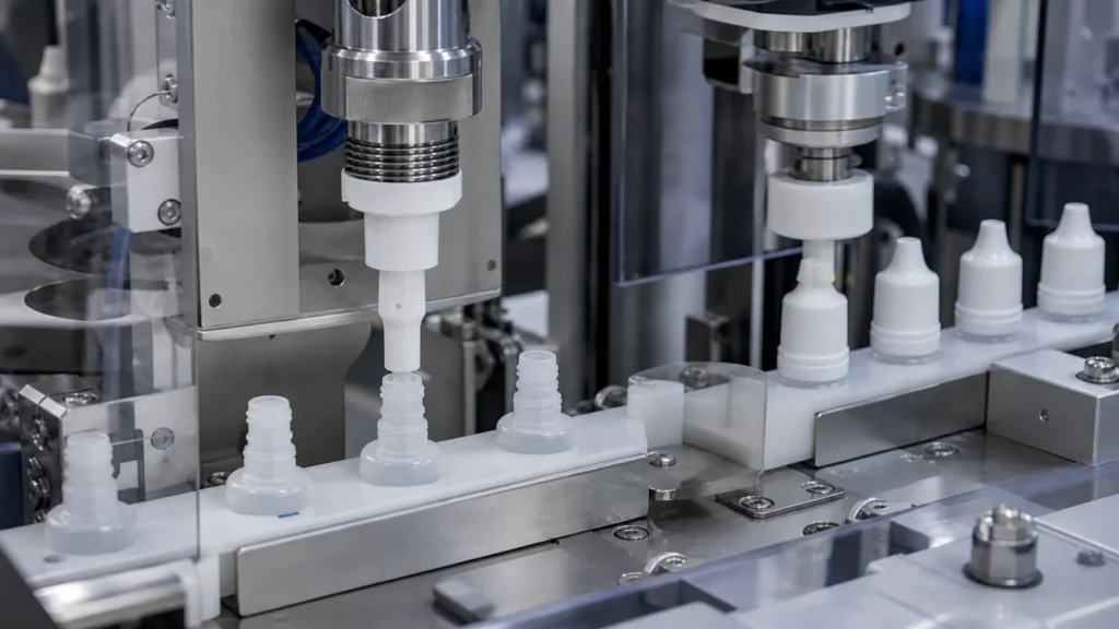
| Stage | Critical control | Failure to prevent |
|---|---|---|
| Container infeed | Clean/sterile component presentation and stable transport | Tipping, contamination, misorientation |
| Small-dose filling | Calibrated dose, clean cutoff, controlled nozzle position | Under/overfill, splash, wet neck, particles |
| Plug insertion | Correct component, orientation, insertion depth and presence | Loose, tilted, damaged or missing plug |
| Cap application | Feed integrity, engagement and defined application control | Cross-thread, loose cap, deformation |
| Inspection/reject | Detect and segregate defined defects with verified logic | Nonconforming unit released or good unit lost |
| Batch records | Trace recipe, alarms, interventions and reconciliation | Weak investigation and release evidence |
A useful line specification follows material flow from sterilized or controlled components through closure and verified rejection. It defines where components are exposed, what protects the critical zone, how operators intervene and how the line returns to a controlled state.
2. Product and component inputs come before machine selection
- Formulation: solution, suspension or emulsion; viscosity, surface tension, foaming, preservative status, light sensitivity and temperature limits.
- Dose: nominal fill range, allowable variation, density, sampling method and whether in-process control is gravimetric, volumetric or both.
- Bottle: material, dimensions and tolerances, neck geometry, opacity, deformation risk and sterilization or component-supply route.
- Plug/dropper: dimensions, orientation, insertion force, target depth, venting behavior, delivered-drop function and defect definitions.
- Cap: thread or snap geometry, tamper-evident features, application window, torque test method and cosmetic limits.
- Output: accepted units per minute by format, batch size, changeover frequency and required integration with upstream/downstream equipment.
FDA’s 2023 draft guidance on topical ophthalmic drug products discusses microbiological quality and container-closure design, delivery and dispensing features. That reinforces an engineering reality: the bottle, plug and cap are functional product-system inputs, not generic consumables to be finalized after ordering the line.
3. Select the sterility concept as a system
The sterility concept should define component preparation, transfer, filling-zone protection, operator access, environmental classification, cleaning and disinfection, sterilization where applicable, monitoring and intervention control. EU GMP Annex 1 emphasizes a contamination control strategy across facility, equipment, personnel, utilities, materials and processes. FDA’s aseptic-processing guidance likewise places product protection in the combined design and control of facilities, equipment and operations.
Discuss whether the line will operate under restricted-access barrier technology or an isolator, how sterile bottles and closures enter, how gloves or access doors are managed, and which interventions are inherent or corrective. The machine supplier should provide interface data and design evidence; the pharmaceutical manufacturer remains responsible for the complete approved process and its validation.
| Design question | Required project answer |
|---|---|
| Where is sterile product exposed? | Map every open-container and open-product step through closure |
| How do components enter? | Define washing/sterilization or ready-to-use transfer and protection |
| What interventions occur? | List routine and non-routine actions, access path and recovery rule |
| How is the zone cleaned? | Specify access, materials, cycles, disinfection and residue considerations |
| What is monitored? | Agree viable/nonviable monitoring interfaces and machine obstructions |
| What happens after a stop? | Define dwell limits, restart checks and product disposition |
4. Small-dose filling: control the whole measurement chain
Small fills magnify systematic error. Specify the usable fill range, not one nominal point; define accuracy and precision with a clear calculation method; and match the pump to formulation behavior. Peristaltic, piston, time-pressure and other technologies have different product-contact, pulsation, cleaning, single-use and changeover implications. Selection should be based on product and process data rather than a universal ranking.
Challenge every nozzle at minimum, nominal and maximum volumes, including start-up and restart after defined dwell times. Confirm balance resolution, tare handling, density conversion, sampling frequency and response to a trend. For suspensions or emulsions, evaluate homogeneity during the run and the effect of hold time or recirculation. For foaming products, test nozzle position and fill profile, not merely pump calibration.
5. Plug insertion: presence is not enough
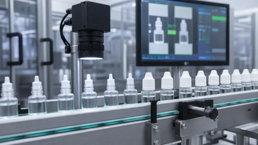
A sensor that confirms a plug passed a point does not prove correct seating. Define plug orientation, insertion depth or height, tilt, damage, insertion force where useful and the relationship between seating and drop delivery. Use approved component samples spanning relevant tolerances and multiple lots when possible.
| Plug defect | Likely mechanism | Useful control or test |
|---|---|---|
| Missing plug | Feed interruption, sensor or transfer fault | Presence detection plus verified reject |
| High/partly seated | Insertion setting, bottle tolerance, wet neck | Height/vision check and destructive depth sampling |
| Tilted plug | Poor centering or unstable bottle transport | Guidance review and camera/attribute inspection |
| Damaged plug | Excess force, sharp contact or component defect | Visual criteria and component-force study |
| Functional drop failure | Orifice, fit or product interaction | Delivered-drop/dispensing test in product-control plan |
Where wetting of the neck or plug contact area can affect seating, connect filling cutoff performance to plug testing. The problem may originate upstream; adjusting insertion force alone may mask rather than solve it.
6. Cap feeding and application control
Cap control begins with feeding: orientation, dust generation, jams and component damage. At application, define the mechanism—threaded, snap-on or another design—and its critical settings. For threaded caps, establish an application and test method that reflects the container-closure system; removal torque may be a useful indicator but should not be treated as a universal proxy for integrity.
Challenge missing, doubled, cross-threaded, cocked and deformed caps. Confirm no-bottle/no-cap logic, cap-present inspection and reject verification. If caps include tamper-evident features, define acceptable engagement and inspection. Test after realistic line stops because queued components and partially completed cycles can create atypical defects.
7. Container transport must protect the critical steps
Stable transport controls nozzle centering, plug placement and capping. Evaluate container accumulation, starwheels or pucks, guides, change parts, stop/start motion and transfer gaps. Lightweight plastic bottles may deform or tip; glass may chip or generate particles if contacts are poorly controlled. The line should minimize contact near critical surfaces and avoid a layout that forces frequent manual correction.
Format changes should use identified parts and repeatable settings. Recipe selection should not compensate for incorrectly installed mechanical parts. Include part verification, line clearance and a first-piece approval process in the changeover design.
8. Inspection and rejection: define detection capability
Create a defect library before choosing sensors or vision. Each defect should have an agreed definition, realistic samples, expected frequency or risk, detection method and reject disposition. Verify detection and rejection as a chain: introduce known defects, confirm the correct signal, track the unit, prove physical segregation and challenge a full or missing reject container.
- Fill presence or fill level, with limitations for opaque containers and foaming products.
- Plug presence, seating height, orientation or damage according to risk and technical feasibility.
- Cap presence, alignment, tamper feature and closure attributes defined by the package system.
- Container damage, tip-over, wrong format and label/serialization interfaces when in scope.
- Reject reconciliation, access control and prevention of re-entry to accepted product flow.
9. Cleaning, qualification and aseptic process evidence
Define which product-contact parts are cleaned in place, sterilized in place, removed for cleaning/sterilization or supplied as single-use assemblies. Review drainability, assembly error prevention, sterile connections, filter interfaces and hold-time assumptions. A machine cleanability demonstration is not cleaning validation; it establishes design capability and evidence for site studies.
Plan FAT, SAT, IQ, OQ, process qualification and aseptic process simulation as connected but distinct activities. FAT can test mechanical functions, recipes, alarms, accuracy and defect handling with approved methods. Site work must address installed utilities, environmental integration, trained operators, production procedures and the validated aseptic process. Electronic records, audit trails and access control should be specified and challenged when part of the system.
10. RFQ checklist for an eye drop filling line
| RFQ input | What to provide |
|---|---|
| Product | Formulation type, viscosity, dose range, temperature and foaming/particle behavior |
| Components | Bottle, plug and cap drawings, samples, tolerances, sterilization/supply route |
| Performance | Accepted output by format, batch size, accuracy criteria and changeover target |
| Sterility | Barrier concept, transfer interfaces, cleaning/sterilization and intervention strategy |
| Inspection | Defect list, detection expectations, challenge samples and reject handling |
| Documentation | URS, risk assessment, FAT/SAT, qualification deliverables and software records |
| Site interfaces | Layout, utilities, HVAC/barrier interfaces, upstream/downstream handshakes and data |
Supplier evaluation questions
- Can the supplier demonstrate stable small-dose performance on all heads with your actual bottle and formulation or a justified simulant?
- How is correct plug seating measured, challenged and linked to rejection—not merely presence detected?
- What prevents an intervention at one station from compromising exposed components at another?
- How are cap application settings established and verified for the specific container-closure system?
- Which qualification documents, software records, calibration evidence and defect challenges are included in the proposal?
FAQ
What is the most important eye drop line specification?
There is no single setting. The most important input is an approved system specification that connects dose, bottle, plug, cap, sterility concept, defects, interventions and validation evidence.
Does an automatic line guarantee sterility?
No. Automation can reduce manipulations, but sterility depends on the validated process and the combined control of facilities, equipment, components, personnel, utilities and operations.
How should plug insertion be checked?
Use a risk-based combination of presence detection, seating-height or vision control, periodic destructive or dimensional checks and functional dispensing tests where applicable.
Is cap torque a container-closure integrity test?
Not by itself. Torque can be a process indicator for some threaded systems, but integrity and package performance need product- and system-specific methods.
What should be tested at FAT?
Test configuration, small-dose accuracy, bottle transport, plug/cap handling, alarms, recipes, defect detection, rejection and documentation with representative samples. Reserve site-dependent sterile-process evidence for approved site qualification and validation.
What information should be sent for a proposal?
Send formulation properties, bottle/plug/cap samples and drawings, fill range, output, sterility concept, inspection needs, utilities, layout and required validation deliverables.