 Skip to content
Last reviewed: September 15, 2026.

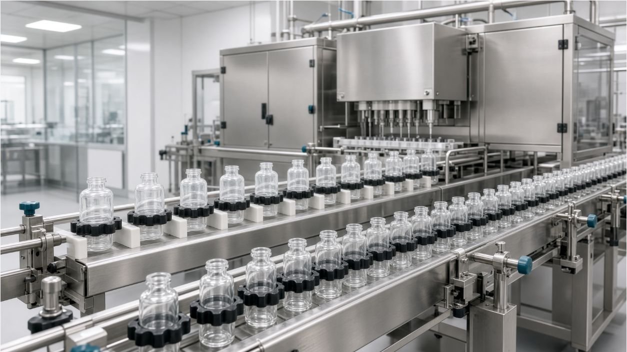
A filling line cannot treat glass and plastic veterinary vials as interchangeable simply because their nominal volume is the same. Container mass, stiffness, base and neck geometry, surface friction, electrostatic behavior, dimensional tolerance, transparency and closure design can change conveying, centering, dosing, inspection and reject performance. The correct decision is based on real drawings, tolerance samples and the product-contact and closure system—not on a generic material ranking.
This article compares only the filling-line changes required when a veterinary project uses glass, plastic or both. It does not repeat a broad list of material advantages and disadvantages. The existing vial filling machine selection guide remains the general equipment-selection page; this page owns shared-line feasibility, static control, change parts and format evidence.
Quick answer: Design or change the line from the container’s actual geometry and behavior. Glass vials often provide greater mass and rigidity but still require protection from contact damage, dimensional variation and particles. Plastic vials may be lighter, more flexible and more prone to static effects, depending on resin, surface, humidity and handling. Compare infeed, guides, holders, starwheels, sensors, nozzle position, closure tooling, inspection lighting and reject handling with both component lots. A shared line is feasible only when qualified change parts and recipes keep each format inside its approved operating and closure window.
1 Start with Drawings, Tolerances and Prepared Samples
Direct answer: Shared-line feasibility begins with dimensioned components and representative tolerance lots, not nominal fill volume or catalogue photographs.
Collect vial overall height, body diameter, neck finish, flange, shoulder, base profile, wall features and critical datums. Include material or resin grade, supplier, molding or forming process, treatment, sterilization or depyrogenation status and incoming packaging presentation. Identify dimensions that control transport, nozzle alignment and closure seating.
Provide stopper, plug, cap, seal or overcap drawings and samples as one container-closure system. A glass vial may use an elastomeric stopper and crimp cap, while a plastic veterinary vial may use a plug, snap fit or screw closure; the actual package defines the line. Avoid assuming that material alone predicts the closing method.
Test more than one component lot where feasible. Prepared or sterilized components can behave differently from development samples. Record lot, measurements, surface condition and any damage so the equipment design can distinguish expected tolerance from a supplier or preparation issue.
| Input | Why it matters | Design output |
|---|---|---|
| Vial drawings and tolerances | Sets contact and datum range | Guides, holders, stars and nozzle center |
| Closure system | Defines feeding and seating | Track, pick tool and closing station |
| Prepared sample lots | Shows real friction and variation | Sensor and transport evidence |
| Product and fill window | Links package to dosing behavior | Pump, nozzle and motion recipe |
2 Compare Conveying Stability by Container Behavior
Direct answer: Conveyor speed, guide pressure and transfer geometry should be tuned to each vial’s mass, stiffness, surface and center of gravity.
Glass containers may carry more inertia and can chip, crack or generate particles if hard contacts, pressure buildup or poor transfers are allowed. Review accumulation, side guides, starwheel entry, dead plates, screw timing and reject handling. Contact materials and gaps should protect the container without sacrificing positive control.
Plastic vials may accelerate quickly, deflect under guide pressure or tip when a narrow base, tall body or low mass meets an abrupt transfer. Wide clearances do not solve instability; they can allow yaw and inconsistent nozzle or closure alignment. Use actual samples to set guide position, belt speed, back pressure and support strategy.
For both materials, challenge minimum and maximum dimensional samples, empty and filled states, startup, accumulation, downstream stop and restart. Record jams, scuffing, container orientation and recovery steps. Nominal steady movement is not enough to approve a shared format.
3 Review Electrostatic Risk for Plastic Vials
Direct answer: Plastic containers require an electrostatic-risk assessment when charging affects feeding, particle attraction, sensors, operator handling or a flammable-vapor hazard.
Charging depends on resin, surface treatment, contact and separation, humidity, speed and nearby materials. Do not assume every plastic vial needs the same ionizer, or that one device guarantees control. First identify the observed or credible failure: vials clinging, closures bridging, dust attraction, false sensing or an ignition concern.
Engineering options may include conductive or dissipative contact materials where compatible, bonding and grounding of metal equipment, controlled humidity where product and facility allow it, reduced friction or drop, ionization, enclosure and housekeeping. The site’s safety specialists must assess any flammable product or vapor under applicable law and standards.
Verify controls at realistic component condition, speed and environment. Measure or observe the relevant response before and after the control, and include alarm, maintenance and cleaning requirements. Static mitigation should solve a defined risk without introducing contamination, airflow or access problems.
| Observed risk | Possible review | Evidence to collect |
|---|---|---|
| Vials cling or misfeed | Friction, humidity, guides and ionization | Feed rate and fault record |
| Dust or particles attract | Airflow, cleaning and charge source | Inspection under defined conditions |
| Sensor instability | Target contrast, grounding and sensor type | Challenge detection results |
| Flammable vapor concern | Site hazard and area-classification review | Approved safety design and tests |

4 Recheck Nozzle Position and Splash Control
Direct answer: Every vial format needs a verified nozzle centerline, entry clearance and dosing motion across the approved tolerance range.
Use the container datum that the machine actually controls, not a drawing center that can shift relative to the guides or holder. Compare neck opening, shoulder, body ovality or flexibility and height. Plastic deflection under handling can change the real opening position even when the nominal dimensions appear compatible.
Define nozzle outside diameter, insertion depth, withdrawal, fill timing, product temperature and any bottom-up motion from representative product behavior. A smaller neck or unstable body may need different centering and motion. Check that the nozzle cannot touch a critical surface under expected tolerance and machine variation.
Challenge startup, normal running, low feed condition, stop and restart for splashing, dripping, strings, foam and closure-zone contamination. The KING PACK liquid filler selection guide provides dosing context; the vial trials must still prove each material and geometry.
5 Select Stopper, Plug or Cap Handling from the Closure
Direct answer: Closure handling changes because of the package design, stiffness, surface and required seating evidence—not merely because the vial is glass or plastic.
Map how stoppers, plugs, caps or seals arrive, are oriented, fed, picked and placed. Define critical surfaces that tooling must not touch, acceptable cosmetic contact and the response to missing, reversed, doubled or damaged components. Prepared closures should be tested in their real presentation.
For stoppered glass systems, review partial or full insertion, vial support, cap placement and crimp or sealing operation as applicable. For plastic systems, review plug insertion, snap fit, thread start, torque or tamper feature as applicable. The owner should define the approved functional and integrity tests for its package.
Test the closure process over component tolerances and line states. Presence detection alone does not prove correct seating. Combine automatic checks with a defined offline measure such as height, force, torque, removal, leak or another approved package-specific test.

6 Design Sensors and Inspection for Both Optical Behaviors
Direct answer: Glass and plastic can require different lighting, backgrounds, sensor positions and algorithms because transparency, color, gloss and surface marks differ.
List required detections: container presence, orientation, fill result, closure presence and seating, cap condition, code and reject confirmation. Assign each defect to an automatic system or approved sample check. Avoid buying a camera by resolution alone; the real question is whether the complete optical setup can distinguish acceptable from defective examples.
Test transparent, tinted, opaque or glossy samples, including natural variation and labels if applied before inspection. Mold lines, bubbles, scuffs and reflections can resemble product or closure defects. Establish controlled reference samples and investigate false accepts and false rejects separately.
Verify reject timing, bin status, full-bin or missing-bin response and reconciliation. A lightweight plastic vial can bounce or leave the reject path differently from glass. Use each filled format during challenge tests and confirm that rejected containers do not re-enter good product flow.
7 Define the Change-Part and Recipe Matrix
Direct answer: A shared line needs a documented list of physical parts, settings, tools, checks and expected changeover sequence for every vial and closure combination.
Review infeed rails, feed screw, starwheels or pucks, side and top guides, holders, nozzle height and center, stopper or cap tooling, sensors, closing head, inspection recipe, labeler if connected and reject timing. Mark parts as common, adjustable or dedicated. Color coding and identification should prevent mix-ups.
Create a parameter list with permitted ranges and access roles. Recipes may control speed, timing, motion, sensor windows and closing settings, but mechanical confirmation remains necessary. Protect validated values from uncontrolled changes and keep revision status aligned with change parts.
Time the full activity: line clearance, part removal, cleaning if required, installation, adjustment, recipe selection, component loading, dry checks, first-off approval and documentation. A fast mechanical swap is not the complete changeover. Use the result for capacity planning and staffing.
| Changeover area | Potential change | Verification |
|---|---|---|
| Container transport | Guides, screw, star, puck or holder | Stable run with tolerance samples |
| Dosing | Nozzle, height, motion and recipe | Dose and closure-zone cleanliness |
| Closing | Track, pick tool and head setting | Seating and functional test |
| Inspection and reject | Lighting, thresholds and timing | Defect challenges and reconciliation |
8 Assess Whether One Line or Two Is Lower Risk
Direct answer: A shared line is justified when change parts and recipes can control both packages without excessive capacity, cleaning, validation or defect risk.
Compare annual demand by format, batch and campaign frequency, required output, changeover time, product loss, staffing, room use and future formats. One flexible line may reduce capital and footprint, while dedicated lines may protect schedule, simplify qualification or prevent difficult cross-format settings. Use the same saleable-output basis for the comparison.
Identify the worst compatibility gaps. A large difference in vial diameter, stability, closure method or inspection behavior can make a nominally flexible line complex. Ask suppliers to state shared modules, dedicated parts, adjustment limits, expected manual work and untested assumptions.
If the project stages one format before another, reserve only interfaces supported by a defined future package. Future-proofing without drawings can create unused hardware. A second-format trial and change-control review should occur before commercial introduction.
9 Build a Representative Sample-Run FAT
Direct answer: The sample-run FAT should expose the handling and closure differences that determine whether glass and plastic can share the equipment.
Provide both vial formats from representative lots, matching closures, approved product or justified surrogate, drawings, target fills, operating range and acceptance methods. Document any limitation caused by unprepared components or surrogate fluid. Set the changeover starting state and time boundary before the test.
For each format, run startup, normal operation, accumulation, downstream stop, restart, low feed and batch end. Record stability, scuffing or damage, static-related behavior, centering, dose, splash, closure result, inspection and reject response. Include tolerance samples and defined faults rather than only ideal components.
Perform the full format change and repeat critical checks. Capture parts used, settings, tools, time, first-off results, deviations and open actions. The evidence should feed the URS, changeover procedure, spares list and site qualification plan.
| Risk | FAT challenge | Required evidence |
|---|---|---|
| Transport | Both formats, tolerance samples and accumulation | Jam, damage and alignment record |
| Static | Real environment and speed | Defined failure response and control result |
| Dosing | Start, run, stop and restart | Dose and splash results |
| Closure | Fault samples and tolerance range | Seating, detection and reject evidence |
| Changeover | Complete format conversion | Parts, settings, time and first-off approval |

10 Keep Package Qualification Separate from Machine Acceptance
Direct answer: Machine acceptance can demonstrate repeatable handling and closing functions, but it cannot establish the complete suitability of a container-closure system.
The product owner should define compatibility, protection, sterility or microbial barrier, integrity, transport, stability and other package studies required for the product and market. 21 CFR 211.94 provides relevant U.S. container-closure context for applicable products, while EU veterinary requirements and marketing authorization commitments must be assessed separately.
Use machine trials to provide controlled samples and process records for those studies. Record component lots, settings, fill conditions, closing data and deviations. Do not infer shelf-life or integrity from appearance, torque or seating height alone.
Link changes in vial or closure supplier, resin, drawing, treatment or preparation process to formal assessment. A format that still fits the guide may behave differently in feeding, static, sealing or inspection. Define when re-testing or requalification is required under the manufacturer’s quality system.
Direct answer: KING PACK can review both vial systems and define the common platform, dedicated change parts, recipes and sample tests required for a defensible shared-line decision.
KING PACK Machinery is a China-based manufacturer of pharmaceutical, veterinary, cosmetic and liquid filling and packaging equipment, with core solutions covering vial and liquid filling, capping, tube filling and sealing, vacuum emulsifying, pet spot-on filling and syringe production systems.
For glass and plastic veterinary vials, the review can cover infeed and accumulation, guides and holders, electrostatic-risk inputs, dosing and nozzles, stopper or cap handling, closing, inspection, rejects, format parts, cleaning access, controls, documentation and FAT. The manufacturer retains responsibility for material, product and package qualification.
Send both vial and closure samples, dimensioned drawings and tolerances, material and preparation details, product properties, fill range, batch and output plan, room conditions, defect list and approved tests through the KING PACK contact page. The KING PACK pharmaceutical and veterinary solutions page provides broader line context while this review remains package specific.
Frequently Asked Questions
Can glass and plastic veterinary vials run on the same filling line?
Yes, when qualified guides, holders, dosing positions, closure tooling, sensors and recipes control both formats. Representative samples and a complete changeover trial are essential.
Do all plastic vials need ionization?
No. Assess whether charging creates a real feeding, particle, sensing, operator or safety risk under the expected resin, speed and environment, then verify the selected control.
Which dimensions matter most?
Body, base, height, neck, finish and the machine-control datums matter, along with stopper, plug or cap dimensions. The critical set depends on each station.
Does the vial material determine the capper?
Not by itself. The actual closure system and approved seating or sealing evidence determine the feed and closing equipment.
Why can one vision recipe fail on both formats?
Transparency, color, gloss, molded features and reflections can change contrast. Lighting, background, optics and thresholds must be challenged with real acceptable and defective samples.
What belongs in a format-change SOP?
Include clearance, parts, cleaning, tools, settings, recipe, mechanical checks, component loading, first-off tests, approvals and records.
What should FAT prove?
FAT should prove stable handling, centering, dosing, closure, inspection, rejection and full changeover for both formats under agreed challenges. It does not prove package shelf-life or integrity.
What should be sent to KING PACK?
Send both vial and closure samples, drawings, tolerances, preparation details, product and fill data, output plan, room conditions, defect list and test methods.
