
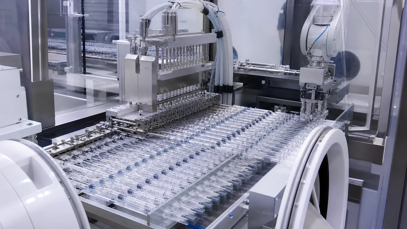
Prefilled syringe defects rarely come from one pump setting. Bubbles, tails, splashing, underfill, overfill and stopper-position variation emerge from the interaction among product rheology, temperature, fluid-path design, nozzle motion, pump profile, vacuum stoppering and inspection rules.
Quick answer: define the defect and acceptance criterion first, then isolate the stage where variation enters. Stabilize product temperature and feed conditions, remove air traps, tune nozzle movement and suck-back, qualify the stopper/vacuum window, and trend fill and stopper data rather than reacting to isolated rejects. Never adopt a generic accuracy claim; use criteria approved for the product and presentation.
Defect map
| Symptom | Likely mechanisms | First checks | Evidence to capture |
|---|---|---|---|
| Bubbles | Air in supply, cavitation, turbulent return, aggressive acceleration | Prime path, joints, inlet head, pump speed | Bubble location, pressure, temperature, cycle phase |
| Drips or tails | Nozzle wetting, weak suck-back, stringy product, long cut-off | Nozzle geometry, cut-off timing, suck-back | High-speed video and drip count |
| Splashing | Nozzle too high, fast initial flow, impact on barrel wall | Start height, velocity profile, centering | Nozzle position and splash pattern |
| Under/overfill | Feed variation, trapped gas, calibration drift, product change | Gravimetric checks, feed level, calibration | Net-weight trend by head and time |
| Stopper variation | Vacuum window, stopper friction, alignment, component tolerance | Stopper lot, vacuum curve, tooling | Position distribution and reject images |
Accuracy, precision and reject criteria
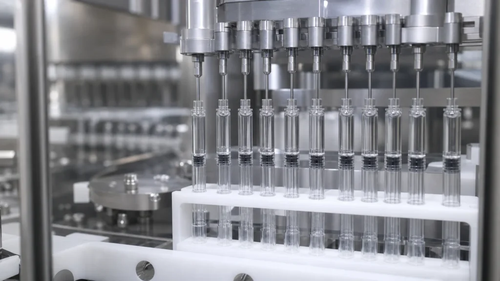
Accuracy describes closeness to the approved target; precision describes repeatability. A filler can repeat the wrong volume precisely, or average near target while individual units vary too widely. The specification should identify the measurement method, tare strategy, density or weight conversion, sampling plan, allowable range and response to a trend.
Separate the process capability target from the registered product specification and from machine FAT criteria. An illustrative engineering window is not a release specification. QA must approve the actual criteria, and the URS should state how the machine records, alarms and rejects.
Where bubbles enter the fluid path
Air can enter at loose connections, an insufficiently flooded inlet, a vortex in the source vessel, empty changeover sections or elastomeric tubing that has not been conditioned. Gas may also come out of solution when pressure or temperature changes. A visible bubble in the syringe therefore does not prove that the nozzle introduced it.
Map the path from vessel to nozzle. Eliminate high points that trap air, reduce unnecessary fittings, confirm gasket compatibility, and define a repeatable prime sequence. Monitor source level and feed pressure. If a pump is run too fast for inlet conditions, cavitation or incomplete chamber filling can create dose variation even when calibration is correct.
Nozzle height and motion control
The nozzle should begin at a position that controls impact and air entrapment without contacting the syringe. Bottom-up filling can reduce foaming for some products, but only if withdrawal speed follows the rising liquid level. If the nozzle climbs too quickly, the stream falls and splashes; too slowly, the tip may become submerged and carry product upward.
Program motion by fill phase: approach, low-flow start, main fill, deceleration, cut-off, suck-back and retract. Check centering across every nest coordinate and at maximum component tolerance. Record recipe limits so operators cannot solve one defect by creating a new contact or throughput risk.
Pump profile and suck-back
Tune acceleration and deceleration before changing the final dose. A rapid start may create turbulence; an abrupt stop may leave a tail. Suck-back can clean the nozzle tip, but excessive reverse movement can draw air into the tip or disturb dose consistency.
Evaluate each head separately and trend by head position. When viscosity or temperature changes, repeat the study rather than assuming the previous profile remains valid. Use representative product whenever possible; a water trial cannot establish behavior for a viscous or protein-sensitive formulation.
Separate calibration error from process variation
A calibration offset moves results away from target; unstable feed conditions widen the result distribution. Investigate both the mean and the spread. If all heads are consistently low, review target conversion, calibration and recipe selection. If only one head drifts, inspect that channel’s tubing, valves, seals and timing. If every head becomes noisy together, check the common vessel, pressure, temperature and prime condition.
Use a controlled challenge rather than changing several settings at once. Hold the dose target constant, record the baseline, make one justified adjustment and collect enough sequential units to see the immediate response and stabilization. Save the old and new recipe versions with the test record. An undocumented operator correction may solve a momentary symptom while making the process harder to reproduce.
Nozzle design and product cut-off
Nozzle bore, tip geometry, surface finish and wetting behavior affect cut-off. A narrow bore may improve placement but raise pressure or shear. A wide bore may reduce shear but form a larger pendant drop. For stringy or tacky products, cut-off depends on the combined motion of pump and nozzle, not only a reverse stroke.
Inspect the product trail after retraction. A tail that touches the barrel wall can become a cosmetic reject or interfere with stoppering. If a nozzle accumulates product over time, include the longest intended run in the trial; ten clean cycles at start-up do not prove sustained control. Define whether routine wiping is allowed, how it is performed within the barrier, and how the intervention is represented in qualification.
Vacuum stoppering and stopper-position control
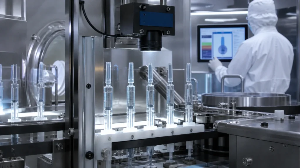
Vacuum stoppering depends on the barrel, stopper, tooling, vacuum level, timing and release profile. Too little vacuum or poor alignment can leave a high stopper. An unstable cycle can widen the distribution. Excessive or poorly controlled vacuum may create other product or component concerns.
Define how stopper position is measured, where the reference surface is located, and whether headspace or plunger movement changes after equilibration. Challenge component lots and dimensional tolerances. Inspection must distinguish a cosmetic position difference from a condition that threatens container closure performance or downstream assembly.
Product temperature and viscosity
Temperature affects viscosity, flow, cut-off behavior and sometimes density. Record product temperature at a meaningful point, not only room temperature. Control hold time and mixing so the first and last syringes in a batch see comparable conditions. For suspensions or emulsions, homogeneity controls must avoid both settling and damaging shear.
Temperature control must include the path, not only the source vessel. Long tubing, unconditioned manifolds and pauses can create a different temperature at the nozzle. Define allowable equilibration time after product connection and after a prolonged stop. If weight is converted to volume, use an approved density value at a defined temperature; otherwise a temperature-driven density change may be misread as a dosing error.
For shear-sensitive products, investigate recirculation and repeated pump passes. A stable net weight does not prove that critical product attributes remain acceptable. Coordinate filling trials with development or analytical teams so dose performance and product integrity are evaluated together.
IPC and checkweigh strategy
Use in-process control to detect drift before it becomes a batch-wide event. A practical plan stratifies samples by filling head, time, nest position, start/restart and batch phase. Gravimetric checks are often useful, provided tare and density assumptions are controlled. Automated feedback should have approved limits and auditability; not every deviation should trigger an automatic correction.
Trend individual results, mean, range and head-specific behavior. Averages can hide one unstable head. Link rejects to time, recipe, component lot, alarms and operator interventions so investigations have context.
Build a sampling plan around sources of variation
Sampling only the first and last units of a batch is rarely informative enough for equipment diagnosis. Stratify the plan across filling heads, nest positions, time, component lots and operating events. Include first units after priming, stopper replenishment and a planned line stop. If a line uses feedback control, capture values before and after each correction so the team can distinguish normal control from over-adjustment.
The measurement system must also be qualified. Confirm balance resolution, calibration, vibration protection, tare method, evaporation risk and data transfer. When checkweighing is destructive or requires manual handling, define how sampled syringes are segregated. Electronic records should identify head, timestamp, recipe and disposition without relying on later manual reconstruction.
Use control limits and specification limits for different purposes. A process trend can trigger investigation before a unit fails its release criterion. Set alert and action logic from development and qualification data, and have QA approve the response. Avoid automatic compensation rules that chase normal measurement noise.
Validation and worst-case runs
Validation should cover minimum and maximum fill volumes, justified viscosity or temperature extremes, start-up, planned stops, restart, replenishment and the longest intended run. Include component lots and formats that challenge alignment or stopper insertion. FDA aseptic-processing guidance and EU GMP Annex 1 both emphasize process design, control and qualification within the site’s contamination-control framework.
Predetermine acceptance criteria and investigation rules. Preserve raw data, calibration status, recipe versions, alarm history and rejected-unit images. A successful average at nominal settings is not evidence that the full operating range is controlled.
Design a defensible challenge matrix
Start with a risk assessment linking material attributes and process parameters to fill mass, bubbles, stopper position, product exposure and container damage. Candidate challenges include minimum and maximum dose, low and high justified viscosity, temperature boundaries, minimum and maximum vessel level, fresh and aged tubing, different component lots, fastest qualified speed and the longest hold or stop.
Not every extreme should be combined if that state cannot occur in production. Define credible worst cases and explain the rationale. FDA’s process-validation guidance promotes a lifecycle approach in which development knowledge supports qualification and continued verification. The equipment study should therefore leave data that can be used for routine monitoring, not just a one-time pass result.
For each run, predetermine sample locations and acceptance rules. Record planned and unplanned interventions, because an acceptable fill distribution can conceal a recovery step that is impractical or contamination-prone. Deviations should state what happened, which units may be affected, the immediate control, the investigation and the retest decision.
Stopper errors beyond vertical position
A stopper can be at the expected depth and still be unsuitable if it is tilted, folded, damaged or associated with uncontrolled headspace. Inspection logic should cover the defect modes relevant to the selected barrel and stopper. The project team must also check how stoppering affects downstream plunger-rod or backstop assembly.
Component friction and dimensional tolerance can vary by lot. Trial more than one representative lot when the risk justifies it, and retain the measurement data rather than only pass/fail totals. Review whether vacuum and insertion settings are recipe-protected, whether sensors detect a missing stopper, and how a partial stoppering event is rejected.
Container closure integrity is a product-system responsibility; a filling-machine trial alone cannot establish it. The machine should create a controlled and documented assembly condition that supports the manufacturer’s validated container-closure program.
Use an evidence-led fault tree
When a defect appears, begin with observable facts: affected head, nest coordinate, time, product temperature, component lot, alarm history and whether the unit followed a stop or replenishment. Then test the shortest plausible branch of causes. Bubbles limited to one head point first to that channel; bubbles across all heads after a vessel change point to the common path or prime sequence.
Photographs and high-speed video are useful when linked to synchronized process data. A picture of a drip without pump position, nozzle position and time cannot show when the tail formed. Similarly, a fill-weight trend without head identity can hide a mechanical channel problem. Design data capture before the trial so evidence can be correlated.
Close troubleshooting by defining the proven operating window, alarm limits, sampling plan and response procedure. Train operators on the evidence needed before changing a recipe. Continued process verification should then watch the same high-value signals so gradual drift is detected early.
When several defects occur together, prioritize the condition with the greatest potential product impact and the earliest common cause. For example, a disturbed prime can produce bubbles, low fills and drips in the same restart sequence. Correcting each symptom with separate recipe adjustments would obscure the shared mechanism. A concise investigation timeline often reveals the common event faster than a large list of unrelated causes.
Troubleshooting checklist
- Confirm the defect definition and approved measurement method.
- Freeze unrelated settings while testing one hypothesis.
- Record product temperature, viscosity reference, level and hold time.
- Inspect and prime the complete fluid path.
- Review nozzle coordinates and motion phase by phase.
- Trend fill results by head, nest position and time.
- Capture the vacuum curve and stopper-position distribution.
- Challenge starts, stops, replenishment and worst-case formats.
- Document the final proven window and recipe access controls.
For equipment context, review what a prefilled syringe filling machine does and the broader aseptic PFS filling guide. King Pack can review fill-volume range, product viscosity and representative defect samples through its pharmaceutical equipment page before a dosing trial is defined.
Frequently asked questions
Can fill accuracy be specified as one percentage for every product?
No. The acceptance criterion depends on dose, product, measurement method, regulatory filing and process risk. Use buyer-approved criteria.
Why do bubbles appear only after a stop?
Air may migrate to a high point during the pause, the nozzle may drain, or restart acceleration may disturb an incompletely primed path. Test stop duration and restart sequence.
Is stronger suck-back always better for dripping?
No. Excessive suck-back can pull air into the tip or change the delivered dose. Optimize it with cut-off timing and nozzle geometry.
How should stopper position be measured?
Use a defined reference surface, measurement timing and validated method. Trend the distribution rather than relying only on visual judgment.
Should FAT use water?
Water can verify basic functions, but it cannot demonstrate behavior for all viscosities, surface tensions or sensitive formulations. Use a justified simulant or representative product where feasible.